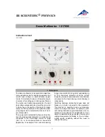


Operation Instructions
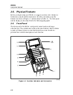
Physical Features
2
2-7
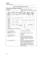
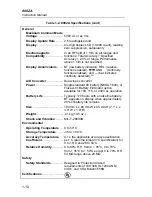
Table 2-1. Controls, Indicators and Connectors
Item
No.
Name
Function
1
W
*
Battery Eliminator
Connector
External input power connector for use with
the A81 Battery Eliminator accessory.
2
Function Buttons:
, REL
Push buttons that toggle on or toggle off the
‘secondary functions: visible or audible
continuity, or relative. These functions are
selected in conjunction with the primary
measurement functions (see items 7 and 8).
3
Battery
Compartment and
Cover
Cover for the 9V battery and the current fuse
F1.
4
V
Ω
S Input
Connector
Protected test lead connector used as the
high input for all voltage, resistance, and
continuity measurements. All test lead
connectors accept standard or safety-
designed banana plugs.
5
COMMON Input
Connector
Protected test lead connector used as the
low or common input for all measurements.
6
A Input Connector
Protected test lead connector used as the
high input for current measurements.
7
Function
Switches: A,V,
Ω
,
Interlocked switches that are used in
conduction with the input connectors to
select the measurement functions. Pushing
one switch releases the other, or both may
be pushed together.
8
AC/DC Function
Switch
Push-on/push-off switch is used to select ac
or dc for current or voltage measurements.
(Does not affect selection of diode test or
resistance functions).
9
Range Switches
Interlocked switches that are used to select
ranges. Pushing a switch selects the
corresponding range and released other
switch depressions. Also used to select
conductance and the diode test.
* For safe operation, fully insert the A81.
Содержание 8062A
Страница 4: ......
Страница 8: ...8062A Instruction Manual iv...
Страница 10: ...8062A Instruction Manual vi...
Страница 12: ...8062A Instruction Manual viii 7 5 A1 Main PCB Schematic Diagram 7 7 7 6 A3 RMS PCB Schematic Diagram 7 8...
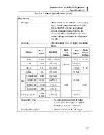
Страница 13: ...1 1 Chapter 1 Introduction and Specifications Contents Page 1 1 Introduction 1 3 1 2 Specifications 1 4...
Страница 14: ...8062A Instruction Manual 1 2...
Страница 24: ...8062A Instruction Manual 2 2...
Страница 50: ...8062A Instruction Manual 2 28...
Страница 52: ...8062A Instruction Manual 3 2...
Страница 62: ...8062A Instruction Manual 3 12...
Страница 64: ...8062A Instruction Manual 4 2...
Страница 90: ...8062A Instruction Manual 4 28...
Страница 92: ...8062A Instruction Manual 5 2...
Страница 97: ...List of Replaceable Parts 5 5 7 Test Button Up 1 of 2 dy37c eps Figure 5 1 8062A Final Assembly...
Страница 98: ...8062A Instruction Manual 5 8 Test Button Up 2 of 2 dy38c eps Figure 5 1 8062A Final Assembly cont...
Страница 102: ...8062A Instruction Manual 5 12 8062A 4031 iv39c eps Figure 5 2 A1 Main PCB Assembly...
Страница 106: ...8062A Instruction Manual 6 2...
Страница 108: ...8062A Instruction Manual 6 4 dy55c eps Figure 6 1 Accessories...
Страница 109: ...Accessory Information Temperature Probes 80T 150C and 80T 150F 6 6 5 dy56c eps Figure 6 1 Accessories cont...
Страница 118: ...8062A Instruction Manual 7 2...
Страница 119: ...Schematic Diagrams 7 7 3 8062A 4031 iv39c eps Figure 7 1 A1 Main PCB Component Locations TopView...
Страница 122: ...8062A Instruction Manual 7 6...
Страница 123: ...8062A Instruction Manual 7 7 8062A 1201 iu46c eps Figure 7 5 A1 Main PCB Schmatic Diagram...
Страница 124: ...8062A Instruction Manual 7 8 8060A 1003 iu61f eps Figure 7 6 A3 RMS PCB Schmatic Diagram...