


Accessory Information
Safety Designed Test Lead Set (TL70)
6
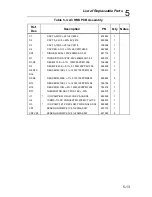
6-11
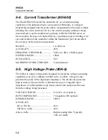
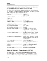
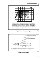
be made without breaking the circuit under test. This coil serves as the
secondary of a 1:1000 transformer. The current-carrying conductor being
measured serves as the primary.
CURRENT RANGE .........................
2A to 150A
ACCURACY, (48 Hz to 10 kHz)......
±
2%, 10A to 150A
±
8%, 2A to 10A
DIVISION RATIO............................
1000:1
WORKING VOLTAGE....................
300V ac rms max
INSULATION DIELECTRIC
WITHSTAND VOLTAGE ...............
3 kV rms
MAXIMUM CONDUCTOR SIZE ...
7/16” (1.11 cm)
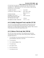
6-12. Safety Designed Test Lead Set (TL70)
The TL70 Test Lead Set includes one red and one black test lead. Each
probe has an anti-slip shoulder near the test tip and is connected to the
multimeter via a safety-designed shrouded banana connector. This set will fit
Fluke instruments with safety-designed input jacks.
6-13. Deluxe Test Lead Set (Y8134)
The Y8134 is a deluxe test lead set. The attachments provided allow
interconnection with a wide variety of leads and electronic components.
Included in the kit are:
1.
Two test leads (one read and one black). The Y8134 leads have a
shrouded banana connectors on each end.
2.
Two test probes
3.
Two insulated alligator clips
4.
Two spade lugs
5.
One squeeze hook
6.
One test lead pouch
7.
One instruction sheet
Содержание 8062A
Страница 4: ......
Страница 8: ...8062A Instruction Manual iv...
Страница 10: ...8062A Instruction Manual vi...
Страница 12: ...8062A Instruction Manual viii 7 5 A1 Main PCB Schematic Diagram 7 7 7 6 A3 RMS PCB Schematic Diagram 7 8...
Страница 13: ...1 1 Chapter 1 Introduction and Specifications Contents Page 1 1 Introduction 1 3 1 2 Specifications 1 4...
Страница 14: ...8062A Instruction Manual 1 2...
Страница 24: ...8062A Instruction Manual 2 2...
Страница 50: ...8062A Instruction Manual 2 28...
Страница 52: ...8062A Instruction Manual 3 2...
Страница 62: ...8062A Instruction Manual 3 12...
Страница 64: ...8062A Instruction Manual 4 2...
Страница 90: ...8062A Instruction Manual 4 28...
Страница 92: ...8062A Instruction Manual 5 2...
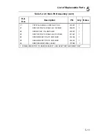
Страница 97: ...List of Replaceable Parts 5 5 7 Test Button Up 1 of 2 dy37c eps Figure 5 1 8062A Final Assembly...
Страница 98: ...8062A Instruction Manual 5 8 Test Button Up 2 of 2 dy38c eps Figure 5 1 8062A Final Assembly cont...
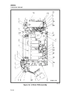
Страница 102: ...8062A Instruction Manual 5 12 8062A 4031 iv39c eps Figure 5 2 A1 Main PCB Assembly...
Страница 106: ...8062A Instruction Manual 6 2...
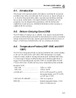
Страница 108: ...8062A Instruction Manual 6 4 dy55c eps Figure 6 1 Accessories...
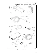
Страница 109: ...Accessory Information Temperature Probes 80T 150C and 80T 150F 6 6 5 dy56c eps Figure 6 1 Accessories cont...
Страница 118: ...8062A Instruction Manual 7 2...
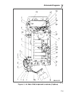
Страница 119: ...Schematic Diagrams 7 7 3 8062A 4031 iv39c eps Figure 7 1 A1 Main PCB Component Locations TopView...
Страница 122: ...8062A Instruction Manual 7 6...
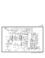
Страница 123: ...8062A Instruction Manual 7 7 8062A 1201 iu46c eps Figure 7 5 A1 Main PCB Schmatic Diagram...
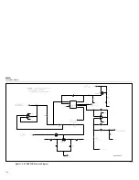
Страница 124: ...8062A Instruction Manual 7 8 8060A 1003 iu61f eps Figure 7 6 A3 RMS PCB Schmatic Diagram...


