


8062A
Instruction Manual
4-26
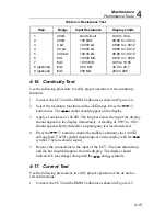
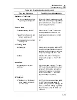
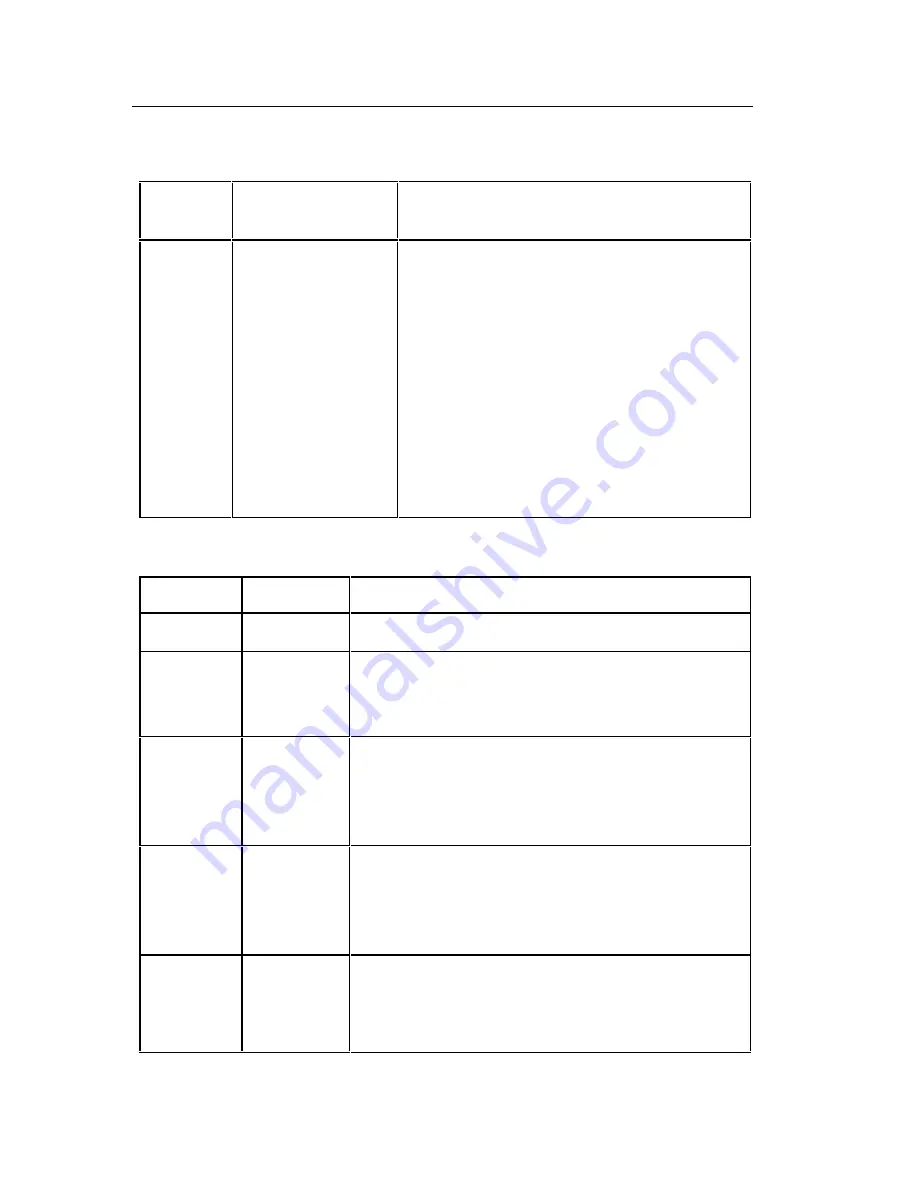
Table 4-7. Troubleshooting the Resistance Function: Voltage Sources
for Ranges
Range
Voltage Source
(
±
10%)
Comment
200
Ω
2 k
Ω
20 k
Ω
200 k
Ω
M
Ω
4.5V
1.2V
1.2V
1.2V
2.1V
These values should be obtained when
no external resistors are connected to
the resistance inputs. Measure voltage
between common (J2) and TP10. Note
that the M
Ω
and 200 k
Ω
ranges will be
loaded by a 10 M
Ω
input impedance.
Use a high impedance voltmeter for the
measurement or decrease the voltage
source magnitude appropriately. A DMM
with a 10 M
Ω
input impedance will read
approximately 1.9V in the M
Ω
range.
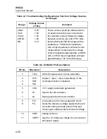
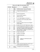
Table 4-8. U3 (MAC) Pin Descriptions
Pin No.
Mnemonic
Description
1
Tone
2.66 kHz square wave to tone generator.
2
3
4
CFO
CM+
CM-
Output, + input, - input, respectively, of the
continuity function comparator.
5
6
7
VSS
HI
LO
-5.1V supply (externally generated).
Input to the a/d converter.
Sense ground for the a/d converter.
8
9
FC+
FC-
Connections to the “flying capacitor” which
stores the reference voltage applied to the a/d
converter during the read period. Plus and
minus signs indicate polarity of stored voltage.
10
11
COM
VREF+
Analog common.
Input for 1V reference voltage for a/d converter
and power supply.
Содержание 8062A
Страница 4: ......
Страница 8: ...8062A Instruction Manual iv...
Страница 10: ...8062A Instruction Manual vi...
Страница 12: ...8062A Instruction Manual viii 7 5 A1 Main PCB Schematic Diagram 7 7 7 6 A3 RMS PCB Schematic Diagram 7 8...
Страница 13: ...1 1 Chapter 1 Introduction and Specifications Contents Page 1 1 Introduction 1 3 1 2 Specifications 1 4...
Страница 14: ...8062A Instruction Manual 1 2...
Страница 24: ...8062A Instruction Manual 2 2...
Страница 50: ...8062A Instruction Manual 2 28...
Страница 52: ...8062A Instruction Manual 3 2...
Страница 62: ...8062A Instruction Manual 3 12...
Страница 64: ...8062A Instruction Manual 4 2...
Страница 90: ...8062A Instruction Manual 4 28...
Страница 92: ...8062A Instruction Manual 5 2...
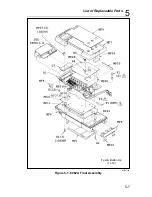
Страница 97: ...List of Replaceable Parts 5 5 7 Test Button Up 1 of 2 dy37c eps Figure 5 1 8062A Final Assembly...
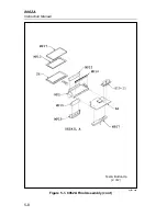
Страница 98: ...8062A Instruction Manual 5 8 Test Button Up 2 of 2 dy38c eps Figure 5 1 8062A Final Assembly cont...
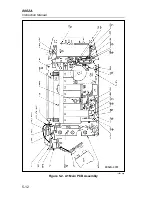
Страница 102: ...8062A Instruction Manual 5 12 8062A 4031 iv39c eps Figure 5 2 A1 Main PCB Assembly...
Страница 106: ...8062A Instruction Manual 6 2...
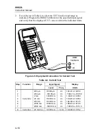
Страница 108: ...8062A Instruction Manual 6 4 dy55c eps Figure 6 1 Accessories...
Страница 109: ...Accessory Information Temperature Probes 80T 150C and 80T 150F 6 6 5 dy56c eps Figure 6 1 Accessories cont...
Страница 118: ...8062A Instruction Manual 7 2...
Страница 119: ...Schematic Diagrams 7 7 3 8062A 4031 iv39c eps Figure 7 1 A1 Main PCB Component Locations TopView...
Страница 122: ...8062A Instruction Manual 7 6...
Страница 123: ...8062A Instruction Manual 7 7 8062A 1201 iu46c eps Figure 7 5 A1 Main PCB Schmatic Diagram...
Страница 124: ...8062A Instruction Manual 7 8 8060A 1003 iu61f eps Figure 7 6 A3 RMS PCB Schmatic Diagram...


