


Operation Instructions
Operation
2
2-17
E
B
E
S
I
M
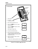
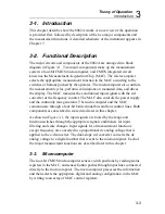
Ammeter Shunt
RI
dy12f.eps
Es = Source Voltage
RI = Load resi Source resistance
Im = Measured current (display reading in amps)
Eb = Burden voltage (calculated)
Eb = meas. current [(200/current range in mA) + .35]
Error:
Error in % = 100 x Eb/(Es - Eb)
Error in A = (Eb x Im)/(Es - Eb)
Example:
ES = 15V
RI = 100 k
Ω
Im = 148.51
µ
A (.14851 mA)
Eb = 148.51 x 10
-6
x [(200/.2) + .35]
= 148.51 x 10
-6
x 1000.35 = 148.56 mV
Max, error in % = 100 x [148.56 mV/(15V - .14856V)] = 1.0003%
Add this to the range spec. accuracy
Max. error in % = 1.0003%
±
(.2% + 2 digits)
Max. error in A = (148.56 mV x 148.51
µ
A)/(15000 mV - 148.56 mV)
= 1.486
µ
A
Add 1.486
µ
A to the reading for correct current
Figure 2-11. Calculating Burden Voltage Error
Содержание 8062A
Страница 4: ......
Страница 8: ...8062A Instruction Manual iv...
Страница 10: ...8062A Instruction Manual vi...
Страница 12: ...8062A Instruction Manual viii 7 5 A1 Main PCB Schematic Diagram 7 7 7 6 A3 RMS PCB Schematic Diagram 7 8...
Страница 13: ...1 1 Chapter 1 Introduction and Specifications Contents Page 1 1 Introduction 1 3 1 2 Specifications 1 4...
Страница 14: ...8062A Instruction Manual 1 2...
Страница 24: ...8062A Instruction Manual 2 2...
Страница 50: ...8062A Instruction Manual 2 28...
Страница 52: ...8062A Instruction Manual 3 2...
Страница 62: ...8062A Instruction Manual 3 12...
Страница 64: ...8062A Instruction Manual 4 2...
Страница 90: ...8062A Instruction Manual 4 28...
Страница 92: ...8062A Instruction Manual 5 2...
Страница 97: ...List of Replaceable Parts 5 5 7 Test Button Up 1 of 2 dy37c eps Figure 5 1 8062A Final Assembly...
Страница 98: ...8062A Instruction Manual 5 8 Test Button Up 2 of 2 dy38c eps Figure 5 1 8062A Final Assembly cont...
Страница 102: ...8062A Instruction Manual 5 12 8062A 4031 iv39c eps Figure 5 2 A1 Main PCB Assembly...
Страница 106: ...8062A Instruction Manual 6 2...
Страница 108: ...8062A Instruction Manual 6 4 dy55c eps Figure 6 1 Accessories...
Страница 109: ...Accessory Information Temperature Probes 80T 150C and 80T 150F 6 6 5 dy56c eps Figure 6 1 Accessories cont...
Страница 118: ...8062A Instruction Manual 7 2...
Страница 119: ...Schematic Diagrams 7 7 3 8062A 4031 iv39c eps Figure 7 1 A1 Main PCB Component Locations TopView...
Страница 122: ...8062A Instruction Manual 7 6...
Страница 123: ...8062A Instruction Manual 7 7 8062A 1201 iu46c eps Figure 7 5 A1 Main PCB Schmatic Diagram...
Страница 124: ...8062A Instruction Manual 7 8 8060A 1003 iu61f eps Figure 7 6 A3 RMS PCB Schmatic Diagram...


