


Maintenance
Introduction
4
4-3
Warning
These servicing instructions are for use by qualified
personnel only. To avoid electric shock, do not perform
any servicing other than that contained in the operating
instructions unless you are qualified to do so.
4-1. Introduction
This chapter of the manual contains information regarding the maintenance
of your instrument. It includes information abut disassembly, performance
tests, calibration adjustments, and troubleshooting. The combined
performance tests are recommended as an acceptance test when the
instrument is first received, and can be used later as a preventive
maintenance tool.
A one-year calibration cycle is recommended to maintain the specifications
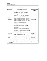
given in Chapter 1 of this manual. The test equipment required for the
performance tests or calibration adjustments is listed in Table 4-1. Test
equipment with equivalent specifications may also be used.
4-2. Service
Information
The 8062A is warranted for a period of one year upon shipment of the
instrument to the original purchaser. Conditions of the warranty are given at
the front of this manual. Malfunctions that occur within the limits of the
warranty will be corrected at no cost to the purchaser. For in-warranty repair,
call (toll-free) 800 426-0361 for the address of the nearest Fluke Technical
Service Center designated to service your instrument (in Alaska, Hawaii,
Washington, or Canada call 206-356-5400). Ship the instrument postpaid in
the original shipping container (if available). Dated proof-of-purchase may
be required for in-warranty repairs.
Fluke Technical Service Centers are also available for calibration and/or
repair of instruments that are beyond the warranty period. Call (toll-free) 800
426-0361 for shipping information. Ship the instrument and remittance in
accordance with instructions received.
Содержание 8062A
Страница 4: ......
Страница 8: ...8062A Instruction Manual iv...
Страница 10: ...8062A Instruction Manual vi...
Страница 12: ...8062A Instruction Manual viii 7 5 A1 Main PCB Schematic Diagram 7 7 7 6 A3 RMS PCB Schematic Diagram 7 8...
Страница 13: ...1 1 Chapter 1 Introduction and Specifications Contents Page 1 1 Introduction 1 3 1 2 Specifications 1 4...
Страница 14: ...8062A Instruction Manual 1 2...
Страница 24: ...8062A Instruction Manual 2 2...
Страница 50: ...8062A Instruction Manual 2 28...
Страница 52: ...8062A Instruction Manual 3 2...
Страница 62: ...8062A Instruction Manual 3 12...
Страница 64: ...8062A Instruction Manual 4 2...
Страница 90: ...8062A Instruction Manual 4 28...
Страница 92: ...8062A Instruction Manual 5 2...
Страница 97: ...List of Replaceable Parts 5 5 7 Test Button Up 1 of 2 dy37c eps Figure 5 1 8062A Final Assembly...
Страница 98: ...8062A Instruction Manual 5 8 Test Button Up 2 of 2 dy38c eps Figure 5 1 8062A Final Assembly cont...
Страница 102: ...8062A Instruction Manual 5 12 8062A 4031 iv39c eps Figure 5 2 A1 Main PCB Assembly...
Страница 106: ...8062A Instruction Manual 6 2...
Страница 108: ...8062A Instruction Manual 6 4 dy55c eps Figure 6 1 Accessories...
Страница 109: ...Accessory Information Temperature Probes 80T 150C and 80T 150F 6 6 5 dy56c eps Figure 6 1 Accessories cont...
Страница 118: ...8062A Instruction Manual 7 2...
Страница 119: ...Schematic Diagrams 7 7 3 8062A 4031 iv39c eps Figure 7 1 A1 Main PCB Component Locations TopView...
Страница 122: ...8062A Instruction Manual 7 6...
Страница 123: ...8062A Instruction Manual 7 7 8062A 1201 iu46c eps Figure 7 5 A1 Main PCB Schmatic Diagram...
Страница 124: ...8062A Instruction Manual 7 8 8060A 1003 iu61f eps Figure 7 6 A3 RMS PCB Schmatic Diagram...


