Introduction and Specifications
Specifications
1
1-9
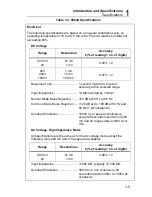
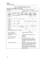
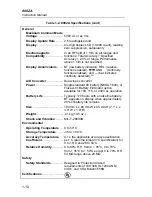
Table 1-2. 8062A Specifications (cont)
AC Current (True RMS Responding, AC-Coupled
Accuracy *......................................
±
(% of r no. of digits). See
table below.
Input
Current
Resolution
Range
20 Hz -
45 Hz
45 Hz -
3 kHz
3 kHz -
10 kHz
10 kHz -
30 kHz
20.00 to
199.99
µ
A
0.01
µ
A
200
µ
A
.2000 to
1.9999 mA
0.1
µ
A
2 mA
2% + 40
2.000 to
19.999 mA
1
µ
A
20 mA
1% + 10 0.75% + 10 2% + 20
20.00 to
199.99 mA
10
µ
A
200 mA
1.5% + 10
1% +10
200.0200 to
1999.9 mA
100
µ
A
2000 mA
Not Specified
* Not specified for input < 10% of scale.
Burden Voltage .............................. 0.3V rms typical except 2000 mA
range, 0.9V rms typical
Overload Protection ....................... 2A/250V fuse (operator replaceable)
in series with 3A/600V fuse (service
personnel replaceable).
Relative
Selection ........................................ When the REL button is pushed, the
input applied at that time is stored as
a zero reference point. Subsequent
readings indicate deviations (
±
) from
the reference point.
Accuracy ........................................ Error does not exceed the sum of the
errors of the reference reading and
the subsequent reading.
Содержание 8062A
Страница 4: ......
Страница 8: ...8062A Instruction Manual iv...
Страница 10: ...8062A Instruction Manual vi...
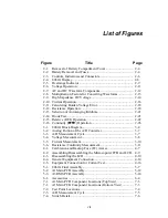
Страница 12: ...8062A Instruction Manual viii 7 5 A1 Main PCB Schematic Diagram 7 7 7 6 A3 RMS PCB Schematic Diagram 7 8...
Страница 13: ...1 1 Chapter 1 Introduction and Specifications Contents Page 1 1 Introduction 1 3 1 2 Specifications 1 4...
Страница 14: ...8062A Instruction Manual 1 2...
Страница 24: ...8062A Instruction Manual 2 2...
Страница 50: ...8062A Instruction Manual 2 28...
Страница 52: ...8062A Instruction Manual 3 2...
Страница 62: ...8062A Instruction Manual 3 12...
Страница 64: ...8062A Instruction Manual 4 2...
Страница 90: ...8062A Instruction Manual 4 28...
Страница 92: ...8062A Instruction Manual 5 2...
Страница 97: ...List of Replaceable Parts 5 5 7 Test Button Up 1 of 2 dy37c eps Figure 5 1 8062A Final Assembly...
Страница 98: ...8062A Instruction Manual 5 8 Test Button Up 2 of 2 dy38c eps Figure 5 1 8062A Final Assembly cont...
Страница 102: ...8062A Instruction Manual 5 12 8062A 4031 iv39c eps Figure 5 2 A1 Main PCB Assembly...
Страница 106: ...8062A Instruction Manual 6 2...
Страница 108: ...8062A Instruction Manual 6 4 dy55c eps Figure 6 1 Accessories...
Страница 109: ...Accessory Information Temperature Probes 80T 150C and 80T 150F 6 6 5 dy56c eps Figure 6 1 Accessories cont...
Страница 118: ...8062A Instruction Manual 7 2...
Страница 119: ...Schematic Diagrams 7 7 3 8062A 4031 iv39c eps Figure 7 1 A1 Main PCB Component Locations TopView...
Страница 122: ...8062A Instruction Manual 7 6...
Страница 123: ...8062A Instruction Manual 7 7 8062A 1201 iu46c eps Figure 7 5 A1 Main PCB Schmatic Diagram...
Страница 124: ...8062A Instruction Manual 7 8 8060A 1003 iu61f eps Figure 7 6 A3 RMS PCB Schmatic Diagram...


