v
List of Tables
Table
Title
Page
1-1.
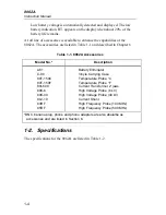
8062A Accessories................................................................... 1-4
1-2.
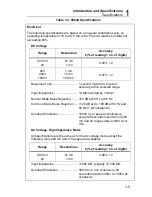
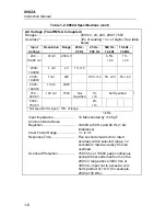
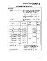
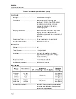
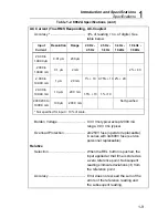
8062A Specifications ............................................................... 1-5
2-1.
Controls, Indicators and Connectors........................................ 2-7
2-2.
Input Overload Limits.............................................................. 2-9
2-3.
Resistance Function Autoranges and Resolution ..................... 2-19
3-1.
Voltage Input Divider .............................................................. 3-9
4-1.
Required Test Equipment ........................................................ 4-4
4-2.
Voltage Test............................................................................. 4-13
4-3.
Resistance Test......................................................................... 4-15
4-4.
Current Test ............................................................................. 4-16
4-5.
Switch Decoding Self-Test ...................................................... 4-21
4-6.
Troubleshooting Guide ............................................................ 4-22
4-7.
Troubleshooting the Resistance Function: Voltage Sources
for Ranges ................................................................................ 4-26
4-8.
U3 (MAC) Pin Descriptions .................................................... 4-26
5-1.
8062A Final Assembly............................................................. 5-5
5-2.
A1 Main PCB Assembly.......................................................... 5-9
5-3.
A3 RMS PCB Assembly.......................................................... 5-13
6-1.
Cables and BNC, Banana, Phone and Phono Plug Adapters ... 6-12
Содержание 8062A
Страница 4: ......
Страница 8: ...8062A Instruction Manual iv...
Страница 10: ...8062A Instruction Manual vi...
Страница 12: ...8062A Instruction Manual viii 7 5 A1 Main PCB Schematic Diagram 7 7 7 6 A3 RMS PCB Schematic Diagram 7 8...
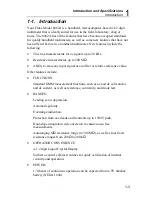
Страница 13: ...1 1 Chapter 1 Introduction and Specifications Contents Page 1 1 Introduction 1 3 1 2 Specifications 1 4...
Страница 14: ...8062A Instruction Manual 1 2...
Страница 24: ...8062A Instruction Manual 2 2...
Страница 50: ...8062A Instruction Manual 2 28...
Страница 52: ...8062A Instruction Manual 3 2...
Страница 62: ...8062A Instruction Manual 3 12...
Страница 64: ...8062A Instruction Manual 4 2...
Страница 90: ...8062A Instruction Manual 4 28...
Страница 92: ...8062A Instruction Manual 5 2...
Страница 97: ...List of Replaceable Parts 5 5 7 Test Button Up 1 of 2 dy37c eps Figure 5 1 8062A Final Assembly...
Страница 98: ...8062A Instruction Manual 5 8 Test Button Up 2 of 2 dy38c eps Figure 5 1 8062A Final Assembly cont...
Страница 102: ...8062A Instruction Manual 5 12 8062A 4031 iv39c eps Figure 5 2 A1 Main PCB Assembly...
Страница 106: ...8062A Instruction Manual 6 2...
Страница 108: ...8062A Instruction Manual 6 4 dy55c eps Figure 6 1 Accessories...
Страница 109: ...Accessory Information Temperature Probes 80T 150C and 80T 150F 6 6 5 dy56c eps Figure 6 1 Accessories cont...
Страница 118: ...8062A Instruction Manual 7 2...
Страница 119: ...Schematic Diagrams 7 7 3 8062A 4031 iv39c eps Figure 7 1 A1 Main PCB Component Locations TopView...
Страница 122: ...8062A Instruction Manual 7 6...
Страница 123: ...8062A Instruction Manual 7 7 8062A 1201 iu46c eps Figure 7 5 A1 Main PCB Schmatic Diagram...
Страница 124: ...8062A Instruction Manual 7 8 8060A 1003 iu61f eps Figure 7 6 A3 RMS PCB Schmatic Diagram...


