


8062A
Instruction Manual
6-10
around conductors up to 3/4 inch in diameter. The pistol shape allows safe,
easy, one-hand operation when making current measurements.
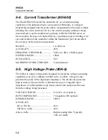
The Model Y8100 probe is battery powered with size AA cells. It measures
current to 200A dc or ac rms using most any voltmeter. Two ranges, 20A and
200A, produce a 2V output at full-range current.
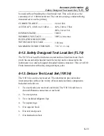
RANGES...........................................
20A ac or dc
200A ac or dc
RATED OUTPUT.............................
2V at full range
ACCURACY
DC to 200 Hz ..................................
200 Hz to 1 kHz ..............................
±
2% of range
<100A add
±
3% reading
>100A add +6% reading
CALIBRATION CYCLE..................
1 year
FREQUENCY RESPONSE ..............
dc to 1.0 kHz
RECOMMENDED LOAD................
≥
3.0 k
Ω
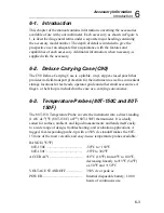
TEMPERATURE RANGE ...............
+15
°
C to +35
°
C; for specified
accuracy -10
°
C to +50
°
C; storage
and operation at reduced accuracy.
HEATING LIMITATION.................
Prolonged operation above 200A ac
or 1 kHz can cause damage to the
Y8100.
WORKING VOLTAGE RATING....
Core to output; 600V dc or 480V ac
maximum output to ground; 42V dc
or 30V ac Max.
APERTURE SIZE.............................
3/4” (19 mm) diameter
SIZE OVERALL...............................
9” x 4-1/2”x 1-7/16” (230 mm x 115
mm x 37 mm)
WEIGHT...........................................
14 ounces (0.4 kg), with batteries
POWER.............................................
Battery, four AA cells
BATTERY LIFE...............................
Alkaline-20 hours continuous
6-11. AC Current Transformer (Y8101)
The Model Y8101 is a small clamp-on current transformer designed to
extend the current measuring capability of an ac current meter up to 150
amperes. A clamp-on coil designed into the probe allows measurements to
Содержание 8062A
Страница 4: ......
Страница 8: ...8062A Instruction Manual iv...
Страница 10: ...8062A Instruction Manual vi...
Страница 12: ...8062A Instruction Manual viii 7 5 A1 Main PCB Schematic Diagram 7 7 7 6 A3 RMS PCB Schematic Diagram 7 8...
Страница 13: ...1 1 Chapter 1 Introduction and Specifications Contents Page 1 1 Introduction 1 3 1 2 Specifications 1 4...
Страница 14: ...8062A Instruction Manual 1 2...
Страница 24: ...8062A Instruction Manual 2 2...
Страница 50: ...8062A Instruction Manual 2 28...
Страница 52: ...8062A Instruction Manual 3 2...
Страница 62: ...8062A Instruction Manual 3 12...
Страница 64: ...8062A Instruction Manual 4 2...
Страница 90: ...8062A Instruction Manual 4 28...
Страница 92: ...8062A Instruction Manual 5 2...
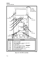
Страница 97: ...List of Replaceable Parts 5 5 7 Test Button Up 1 of 2 dy37c eps Figure 5 1 8062A Final Assembly...
Страница 98: ...8062A Instruction Manual 5 8 Test Button Up 2 of 2 dy38c eps Figure 5 1 8062A Final Assembly cont...
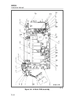
Страница 102: ...8062A Instruction Manual 5 12 8062A 4031 iv39c eps Figure 5 2 A1 Main PCB Assembly...
Страница 106: ...8062A Instruction Manual 6 2...
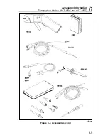
Страница 108: ...8062A Instruction Manual 6 4 dy55c eps Figure 6 1 Accessories...
Страница 109: ...Accessory Information Temperature Probes 80T 150C and 80T 150F 6 6 5 dy56c eps Figure 6 1 Accessories cont...
Страница 118: ...8062A Instruction Manual 7 2...
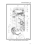
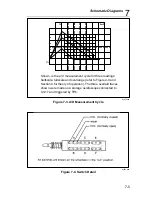
Страница 119: ...Schematic Diagrams 7 7 3 8062A 4031 iv39c eps Figure 7 1 A1 Main PCB Component Locations TopView...
Страница 122: ...8062A Instruction Manual 7 6...
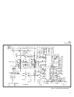
Страница 123: ...8062A Instruction Manual 7 7 8062A 1201 iu46c eps Figure 7 5 A1 Main PCB Schmatic Diagram...
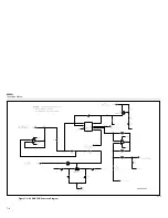
Страница 124: ...8062A Instruction Manual 7 8 8060A 1003 iu61f eps Figure 7 6 A3 RMS PCB Schmatic Diagram...


