


Operation Instructions
Operation
2
2-15
Note
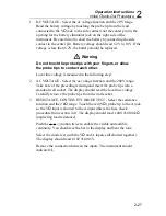
When taking measurements in the high impedance dc voltage
function, do not select any ranges except the 2V or 200 mV ranges.
Measurement in other ranges will result in erroneous readings.
Note
When the high impedance dc voltage function is selected and no
inputis applied, noise from the environment (such as rf or power
line noise) may cause the 8062A to display OL (overrange).
2-16. AC/DC Current (A)
Selection of the ac or dc current (A) function is described in Figure 2-10.
The 8062A offers five ac (true rms ac-coupled) and five dc current ranges:
200
µ
A, 2 mA, 20 mA, 200 mA, 2000 mA. Each range is protected by a
2A/250V fuse in series with a 3A/600V fuse.
When a meter is placed in series with a circuit to measure current, you may
have to consider an error caused by the voltage drop across the meter (in this
case, across the protective fuses and current shunts). This voltage drop is
called the burden voltage. The maximum full-scale burden voltages for the
8062A are 0.3V for the four lowest ranges and 0.9V for the highest range.
These voltage drops can affect the accuracy of a current measurement if the
current source is unregulated and the resistance of the shunt and fuses
represents a significant part (1/1000 or more) of the source resistance. If
burden voltage does present a problem, you can calculate the error by using
the formula in Figure 2-11. You can minimize this error by selecting the
highest current range that provides the necessary resolution.
Содержание 8062A
Страница 4: ......
Страница 8: ...8062A Instruction Manual iv...
Страница 10: ...8062A Instruction Manual vi...
Страница 12: ...8062A Instruction Manual viii 7 5 A1 Main PCB Schematic Diagram 7 7 7 6 A3 RMS PCB Schematic Diagram 7 8...
Страница 13: ...1 1 Chapter 1 Introduction and Specifications Contents Page 1 1 Introduction 1 3 1 2 Specifications 1 4...
Страница 14: ...8062A Instruction Manual 1 2...
Страница 24: ...8062A Instruction Manual 2 2...
Страница 50: ...8062A Instruction Manual 2 28...
Страница 52: ...8062A Instruction Manual 3 2...
Страница 62: ...8062A Instruction Manual 3 12...
Страница 64: ...8062A Instruction Manual 4 2...
Страница 90: ...8062A Instruction Manual 4 28...
Страница 92: ...8062A Instruction Manual 5 2...
Страница 97: ...List of Replaceable Parts 5 5 7 Test Button Up 1 of 2 dy37c eps Figure 5 1 8062A Final Assembly...
Страница 98: ...8062A Instruction Manual 5 8 Test Button Up 2 of 2 dy38c eps Figure 5 1 8062A Final Assembly cont...
Страница 102: ...8062A Instruction Manual 5 12 8062A 4031 iv39c eps Figure 5 2 A1 Main PCB Assembly...
Страница 106: ...8062A Instruction Manual 6 2...
Страница 108: ...8062A Instruction Manual 6 4 dy55c eps Figure 6 1 Accessories...
Страница 109: ...Accessory Information Temperature Probes 80T 150C and 80T 150F 6 6 5 dy56c eps Figure 6 1 Accessories cont...
Страница 118: ...8062A Instruction Manual 7 2...
Страница 119: ...Schematic Diagrams 7 7 3 8062A 4031 iv39c eps Figure 7 1 A1 Main PCB Component Locations TopView...
Страница 122: ...8062A Instruction Manual 7 6...
Страница 123: ...8062A Instruction Manual 7 7 8062A 1201 iu46c eps Figure 7 5 A1 Main PCB Schmatic Diagram...
Страница 124: ...8062A Instruction Manual 7 8 8060A 1003 iu61f eps Figure 7 6 A3 RMS PCB Schmatic Diagram...


