


Technical Documentation
VeriSens
®
v2.11.0-B4
387/429
Baumer Optronic GmbH
Radeberg, Germany
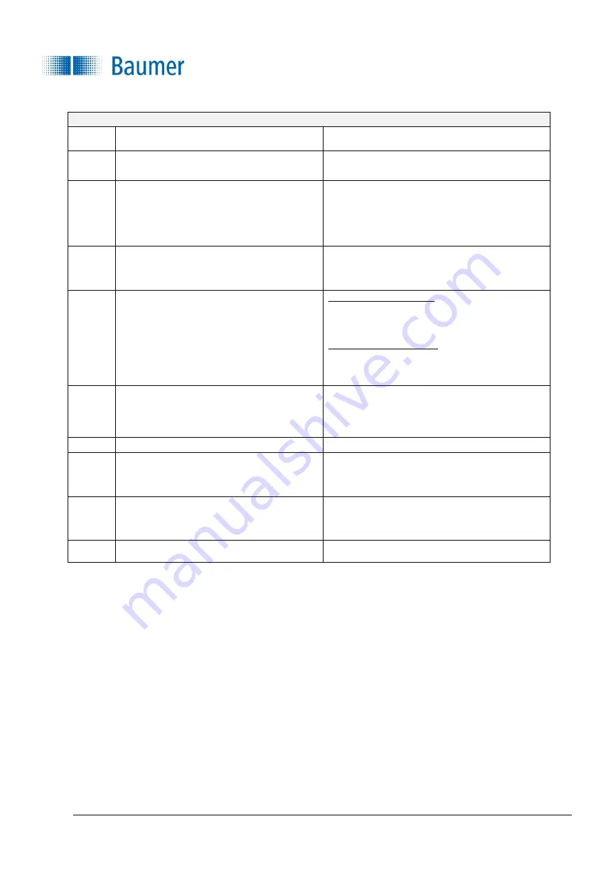
3.
Performing coordinate adjustment in URCap
O
Check for Z calibration, otherwise repeat Step
"K".
P
Selection: Choose the type of vision sensor
assembly (dynamic or stationary).
Q
Selection: By default, the coordinate system
should be set to "Base", otherwise it must be
ensured that the Z-axis of the coordinate
system has the same Z-axis as the
SmartGrid
.
R
For dynamically installed vision sensors: UR
should be in the appropriate pose, the stored
installation pose is optimal.
S
Dynamic vision sensor:
Place the SmartGrid
at
object height, i.e. in the range of a good depth
of field
Stationary vision sensor: The
SmartGrid
is
clamped in the robot and driven with it to the
height of the object to be examined (optimum
depth of field).
T
Since all height distances are referenced to a
reference level, the distance from the top of
the
SmartGrid
to the reference level must be
entered here.
U
Press Initiate "coordinate adjustment"
V
Drive waypoints using both translation (at least
twice 10mm) and rotation (at least two times 5
°).
W
If the calibration quality is at least "good", you
can complete the calibration.
X
Complete the calibration with "Complete".


