


2 Functions
60
7ST6 Manual
E50417-G1176-C251-A3
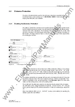
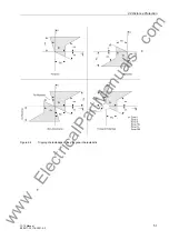
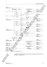
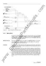
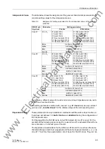
Figure 2-11
Logic of change to zone, example zone Z1
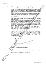
2.2.9
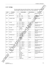
Setting Notes
At address
1201
FCT Distance
the distance protection function can be switched
ON
or
OFF
. At address
113
DISTANCE CURVE
the characteristic types
Quadrilateral
and
Combined
can be selected (see Subsection 2.1.1.2). This setting is valid for all
characteristics of the distance protection.
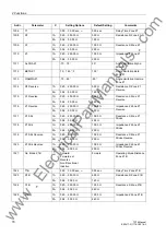
Minimum Current
The minimum phase current is set in address
1202
Minimum Iph>
. The minimum
current for fault detection
Minimum Iph>
is set a little (approx. 10 %) below the
minimum short-circuit current that may occur.
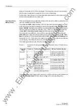
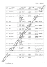
Load Area
For the description of the parameters of the load range in this section, general desig-
nations will be used. Table 2-2 shows the assignment of these designations to the con-
crete parameters of a zone.
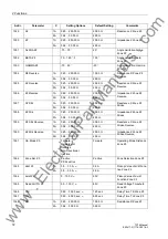
On long, highly loadable lines there is a risk of the load impedance rising as high as
the tripping area of the distance protection. In order to avoid spurious pickup of the dis-
tance protection during the transfer of high powers, the load range can be set so as to
exclude such spurious capture due to overloads. This load range has been taken into
account for the description of the tripping characteristics (see margin headings „Com-
bined Characteristics“ and „Polygonal Characteristics“). The R value is set somewhat
(approx. 10 %) below the minimum expected load impedance. The minimum load im-
pedance results when the maximum load current and minimum operating voltage
exist.
www
. ElectricalPartManuals
. com