


2 Functions
198
7ST6 Manual
E50417-G1176-C251-A3
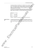
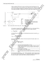
Figure 2-65
Standard interlockings
1)
Source of Command REMOTE includes LOCAL.
LOCAL
Command using substation controller
REMOTE
Command via telecontrol station to power system management and from power system management to the
device
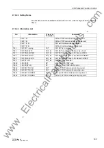
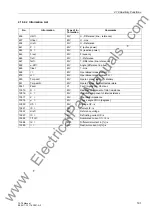
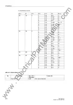
The display shows the configured interlocking reasons. The are marked by letters as
explained in Table 2-11.
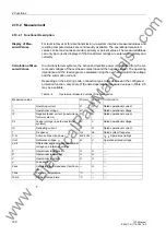
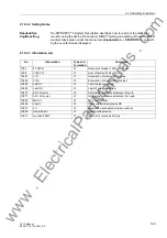
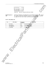
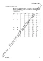
Table 2-11
Interlocking Commands
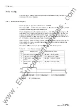
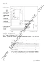
Figure 2-66 shows all interlocking conditions (which usually appear in the display of
the device) for three switchgear items with the relevant abbreviations explained in
Table 2-11. All parameterised interlocking conditions are indicated.
Interlocking Commands
Command
Display
Switching Authority
L
L
System Interlocking
S
S
Bay Interlocking
Z
Z
SET = ACTUAL (switch direction check)
P
P
Protection Blockage
B
B
www
. ElectricalPartManuals
. com