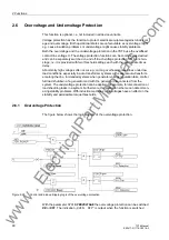

2 Functions
80
7ST6 Manual
E50417-G1176-C251-A3
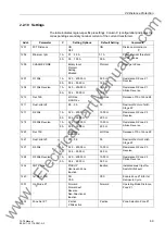
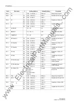
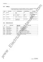
High-set Current
Stage I>>
With the parameter
I>>
(address
2608
) the pickup threshold of the high-set current
stage is specified.
When using a personal computer and DIGSI
®
to apply the settings, these can be op-
tionally entered as primary or secondary values. If secondary quantities are used, all
currents must be converted to the secondary side of the current transformers.
The delay time of the very high set current stage
T I>>
is set in address
2609
.
The delay set is in addition to the pickup time which does not include the operating
time (measuring time).
The dropout to pickup ratio of the stage is 0.95.
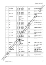
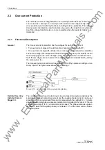
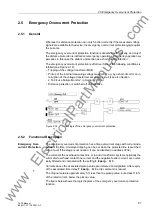
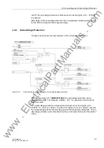
Overcurrent Stage
I> in Definite-time
Overcurrent Pro-
tection
If the overcurrent stage is to be operated as a definite-time overcurrent protection,
address
2602
CURVE O/C
must be set to
Definite Time
.
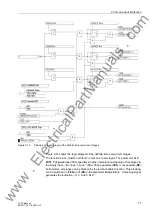
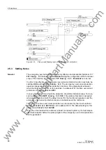
For the setting of the current pickup value,
I>
(address
2614
), the maximum operat-
ing current is most decisive. Pickup due to overload should never occur, since the
device in this operating mode operates as fault protection with correspondingly short
tripping times and not as overload protection. Therefore, the pickup value is set to
about 20 % above the maximum expected overload.
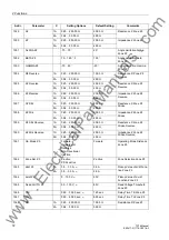
When using a personal computer and DIGSI
®
to apply the settings, these can be op-
tionally entered as primary or secondary values. If secondary quantities are used, all
currents must be converted to the secondary side of the current transformers.
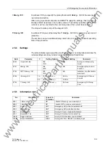
The time delay
T I>
(address
2615
) results from the time grading schedule designed
for the network. If implemented as emergency overcurrent protection, shorter tripping
times are advisable (one grading time step above the fast tripping stage), as this func-
tion is only activated in the case of the loss of the local measured voltage.
The delay set is in addition to the pickup time which does not include the operating
time (measuring time).
The dropout to pickup ratio of the stage is 0.95.
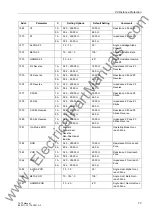
Overcurrent Stage
IP in Inverse-time
Overcurrent Pro-
tection with IEC
Characteristics
If the overcurrent stage is to be operated as an inverse-time stage with IEC character-
istics, address
2602
CURVE O/C
must be set to
TOC IEC
.
With IEC characteristics, the following characteristics are available in address
2611
IEC Curve
:
Normal Inverse
(inverse, type A according to IEC 60255-3),
Very Inverse
(very inverse, type B according to IEC 60255-3),
Extremely Inv.
(extremely inverse, type C according to IEC 60255-3), and
LongTimeInverse
(longtime, type B according to IEC 60255-3).
For the setting of the pickup value
IP
(address
2617
), the following must be observed:
Pickup only occurs at a current which is approximately 10 % above the set value. The
dropout threshold is the setting value.
The time multiplier
T IP
(address
2618
) derives from the time grading schedule set
for the network.
www
. ElectricalPartManuals
. com