
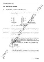


3.2 Checking Connections
239
7ST6 Manual
E50417-G1176-C251-A3
• The short-circuit feature of the current circuits of the device is to be checked. This
may be performed with an ohmmeter or other test equipment for checking continu-
ity. Make sure that terminal continuity is not wrongly simulated in reverse direction
via current transformers or their short circuit links.
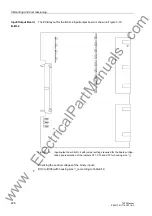
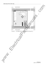
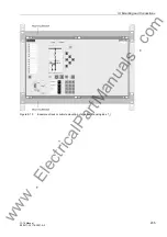
– Remove the screws of the front cover.
– Remove the ribbon cable connected to the I/O board with the measured current
inputs (on the front side it is the right printed circuit board). Furthermore, remove
the printed circuit board so that there is no more contact anymore with the plug-
in terminal of the housing.
– Check continuity on the connection side, for each current connection pair.
– Insert the board again firmly; press the ribbon cable with care. Avoid to bend con-
nection pins! Do not apply force!
– At the terminals of the device, again check continuity for each pair of terminals
that receives current from the CTs.
– Reinstall the front cover and tighten it with screws.
• Connect an ammeter in the supply circuit of the power supply. A range of about 2.5
A to 5 A for the meter is appropriate.
• Switch on mcb for auxiliary voltage (supply protection), check the voltage level and,
if applicable, the polarity of the voltage at the device terminals or at the connection
modules.
• The current input should correspond to the power input in neutral position of the
device. The measured steady state current should be insignificant. Transient move-
ment of the ammeter merely indicates the charging current of capacitors.
• Switch off mcb for the auxiliary power supply.
• Remove ammeter; re-establish normal auxiliary voltage connection.
• Switch on mcb for the auxiliary power supply.
• Switch on voltage transformer protective circuit breaker.
• Switch off mcb for the voltage transformers and the auxiliary power supply.
• Check the trip and close circuits to the power system circuit breakers.
• Check control lines from and to the other devices.
• Check signalling lines.
• Switch on m.c.b.
www
. ElectricalPartManuals
. com