


2.15 It Function (current-time integral)
161
7ST6 Manual
E50417-G1176-C251-A3
2P Calculation
The application of the two-point procedure for the calculation of the remaining lifespan
depends on the 2P configuration.
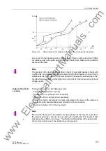
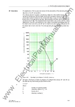
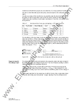
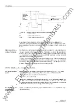
The CB manufacturer supplies a double-log diagram on the relation between the
number of operating cycles and fault currents (see example in figure 2-45). This
picture also serves to determine the still possible trips (in case of a trip with the same
fault current). Considering this example, approximately 1000 trips can be executed for
a fault current of 10kA. The characteristic is determined by two vertices and the linking
straight line. Point P1 is determined by the number of permitted operating cycles for
the rated normal current
I
r, point P2 by the maximum number of operating cycles for
the rated short-circuit current
I
sc. The corresponding four values can be parameter-
ised.
Figure 2-45
Operating Cycle Diagram for the 2P-procedure
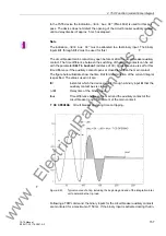
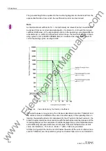
As figure 2-45 shows a double-log diagram, the straight line between P1 and P2 can
be expressed by the following exponential function:
n = b·
I
b
m
where:
n.
Number of operating cycles
b.
Operating cycles for
I
b
= 1A
I
b
. Fault
current
m. Direction
coefficient
www
. com