


2 Functions
68
7ST6 Manual
E50417-G1176-C251-A3
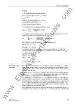
Calculation example:
15 kV infeed with the following impedance from the infeed point to the location of the
voltage transformer: Z = (2 + j 7)
Ω
(corresponds to e.g. 23.5 km Re200 with amplifi-
cation line one-track at 50 Hz, or 29 km Re330 two-track without return-line cable and
amplification line)
Maximum start-up current primary: I
bmax
= 550 A
Minimum infeed voltage: Umin = 15 kV · 0.9
Voltage transformer: 15 kV / 0.1 kV
From the above values, the following minimum voltage in operation results:
Setting value secondary: USec=15kV/0.1kV· 9.5kV= 63.3V
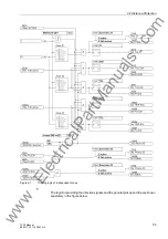
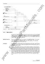
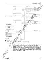
By setting the du/dt or di/dt parameters to 0, the grading margin
T2K
or
T3K
is re-
leased; at the same time the timers
T2L
and
T3L
are blocked. This blocking is sig-
nalled by the indication
„Dis. T2K active“
or
„Dis. T3K active“
.
By setting the du/dt or di/dt parameters to infinite, the corresponding parts of the short-
circuit detection are disabled.
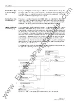
By setting the di/dt and du/dt parameter to "
∞
", the stage T2L (T3L) is always activat-
ed. With another setting than "
∞
" the indications "Z2(Z3)di/dt active" or "Z2(Z3)du/dt
active" are output.
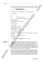
Note
The setting of “
∞
“ is equally possible in DIGSI via “oo“ or directly at the device via “
..
“.
www
. ElectricalPartManuals
. com