

3.1 Mounting and Connections
223
7ST6 Manual
E50417-G1176-C251-A3
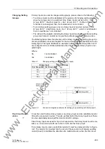
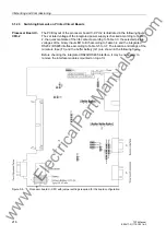
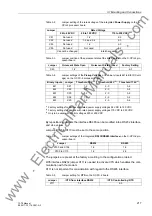
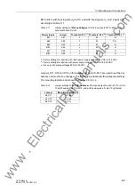
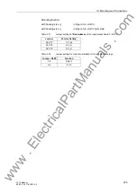
Table 3-14
Jumper settings of
Pickup Voltages
of the binary input BI6 on the input/output
board C-I/O-12
1)
Factory settings for devices with rated power supply voltages 24 VDC to 125 VDC
2)
Factory settings for devices with rated power supply voltages 110 VDC to 250 VDC
3)
Use only with pickup voltages 220 to 250 VDC
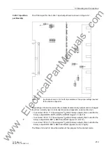
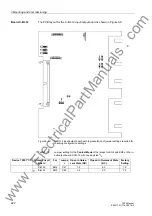
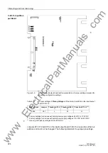
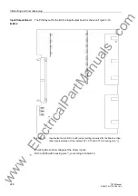
Jumpers X71, X72 and X73 on the input/output board C-I/O-12 are used to set the bus
address and must not be changed. The following table lists the jumper presettings.
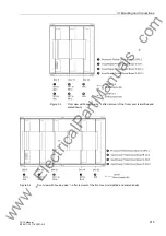
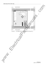
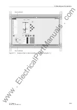
Mounting location:
with housing size
1
/
2
: in Figure 3-3, slot 33
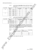
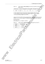
Table 3-15
Jumper settings of
Board Address
of the input/output board C-I/O-12
Binary Input
Jumper Threshold 19 V
Threshold 88 V
Threshold 176 V
BI6
X21
L
M
H
Jumper
Factory Setting
A0 X71
1-2 (H)
A1 X72
2-3 (L)
A2 X73
2-3 (L)
www
. ElectricalPartManuals
. com