


2.2 Distance Protection
63
7ST6 Manual
E50417-G1176-C251-A3
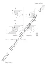
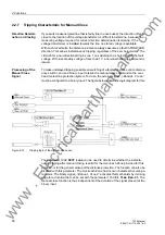
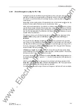
inception. Accordingly the directional characteristic includes a safety margin with
respect to the limits of the first quadrant in the R–X diagram. This safety margin is
defined by the parameters
Beta
(
β
) and
Gamma
(
γ
). Normally the default settings of
these parameters need not be changed. For highly loaded overhead contact lines, the
use of network calculation software is recommended to determine the setting values.
Figure 2-12
Directional characteristic
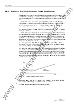
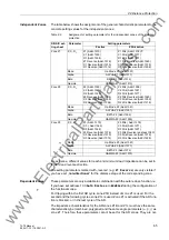
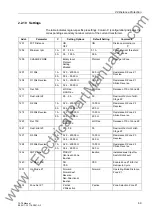
Combined Charac-
teristics
If the distance protection is to have impedance curves with combined characteristic,
set address
113
DISTANCE CURVE
=
Combined
.
For the description of the characteristic parameters in this section, general designa-
tions will be used. Table 2-2 shows the assignment of these designations to the actual
parameters of a zone.
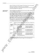
The reach of the characteristic is set with the parameter
Z
. Here you set the absolute
value of the balance point impedance, without taking into account an arc resistance
for the zone. For more information on setting the reach, please refer to margin heading
„Grading Coordination Chart“.
The load range is set with the parameters for the minimum load impedance
R
L
and the
spread angle of the load range
Alpha
(
α
). For more information on setting the load
range parameters, please refer to margin heading „Load Range“.
The safety margins of the directional characteristic are set in the parameters
Beta
(
β
)
and
Gamma
(
γ
) (see margin heading „Determination of Direction“).
www
. ElectricalPartManuals
. com