


2.2 Distance Protection
61
7ST6 Manual
E50417-G1176-C251-A3
Example:
15 kV overhead contact line with the data:
Maximum transmitted power S
Max
= 10 MVA
I
LMax
= 784 A
Minimum operating voltage U
Min
= 0.85 U
N
Current transformers 1000 A / 1 A
Voltage transformers 15 kV/0.1 kV
The resulting minimum load impedance is therefore:
This value can be entered as a primary value when parameterizing with a PC and
DIGSI®. Conversion to secondary quantities is:
When applying a security margin of 10 % the following is set:
Primary: R
L
= 14.63
Ω
or
Secondary: R
L
= 97.53
Ω
.
The spread angle of the load range „
α
“ must be greater (approx. 10
°
) than the
maximum arising load angle (corresponding to the minimum power factor cos
ϕ
Min
).
Calculation example:
Minimum power factor:
cos
ϕ
Min
= 0.63
ϕ
max
= 51
°
Setting value
α
=
ϕ
max
+ 5
°
= 56
°
.
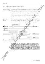
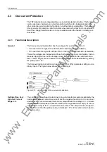
Grading Coordina-
tion Chart
It is recommended to initially create a grading coordination chart for the entire galvan-
ically interconnected system. This diagram should reflect the line lengths with their
primary reactances X´ in
Ω
/km. For the reach of the distance zones, the reactance X
is the deciding quantity.
The first zone Z1 is usually set to cover 85 % of the protected line without any trip time
delay (i.e. T1 = 0.00 s). The protection clears faults in this range without additional
time delay, i.e. the tripping time is the relay basic operating time.
The tripping time of the higher zones is sequentially increased by one time grading
margin. The grading margin must take into account the circuit breaker operating time
including the spread of this time, the resetting time of the protection equipment as well
as the spread of the protection delay timers. Typical values are 0.2 s to 0.4 s. The
reach is selected to cover up to approximately 80 % of the zone with the same set time
delay on the shortest neighbouring feeder.
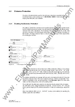
When using a personal computer and DIGSI® to apply the settings, these can be op-
tionally entered as primary or secondary values. In the case of parameterization with
www
. ElectricalPartManuals
. com