


3.4 Final Preparation of the Device
253
7ST6 Manual
E50417-G1176-C251-A3
3.4
Final Preparation of the Device
The used terminal screws must be tightened, including those that are not used. All the
plug connectors must be correctly inserted.
Caution!
Do not apply force!
The tightening torques must not be exceeded as the threads and terminal chambers
may otherwise be damaged!
The setting values should be checked again, if they were changed during the
tests.
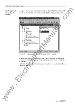
Check if protection, control and auxiliary functions to be found with the configu-
ration parameters are set correctly (Section 2.1.1, Functional Scope). All desired ele-
ments and functions must be set to
ON
. Keep a copy of all of the in-service settings on
a PC.
Check the internal clock of the device. If necessary, set the clock or synchronize the
clock if the element is not automatically synchronized. Further details on this subject
are described in /1/.
The indication buffers are deleted under
Main Menu
→
Annunciation
→
Set/Re-
set
, so that in the future they only contain information on actual events and states.
The numbers in the switching statistics should be reset to the values that were existing
prior to the testing.
The counters of the operational measured values (e.g. operation counter, if available)
are reset under
Main Menu
→
Measurement
→
Reset
.
Press the
ESC
key, several times if necessary, to return to the default display.
Clear the LEDs on the front panel by pressing the
LED
key, so that they only show real
events and states. In this context, saved output relays are reset, too. Pressing the
LED
key also serves as a test for the LEDs on the front panel because they should all light
when the button is pressed. If the LEDs display states relevant by that moment, these
LEDs, of course, stay lit.
The green „RUN“ LED must light up, whereas the red „ERROR“ must not light up.
Close the protective switches. If test switches are available, then these must be in the
operating position.
The device is now ready for operation.
■
www
. ElectricalPartManuals
. com