


3.1 Mounting and Connections
209
7ST6 Manual
E50417-G1176-C251-A3
Changing Setting
Groups
If binary inputs are used to change setting groups, please observe the following:
• Two binary inputs must be dedicated to the purpose of changing setting groups
when four groups are to be switched. One binary input must be set for
„>Set
Group Bit0“
, the other input for
„>Set Group Bit1“
. If either of these input
functions is not assigned, then it is considered as not controlled.
• To control two setting groups, only one binary input is required, namely
„>Set
Group Bit0“
, since binary input
„>Set Group Bit1“
, which is not allocated,
then is classified as “not controlled”.
• The status of the signals controlling the binary inputs to activate a particular setting
group must remain constant as long as that particular group is to remain active.
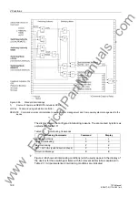
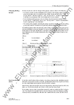
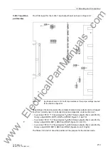
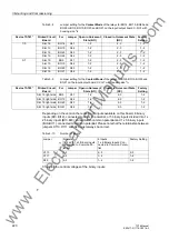
The following table shows the allocation of the binary inputs to the setting groups A to
D and a simplified connection diagram for the two binary inputs is illustrated in the fol-
lowing figure. The figure illustrates an example in which both Set Group Bits 0 and 1
are configured to be controlled (actuated) when the associated binary input is ener-
gized (high).
Where:
No
= not controlled
Yes
= controlled
Table 3-1
Changing setting groups using binary inputs
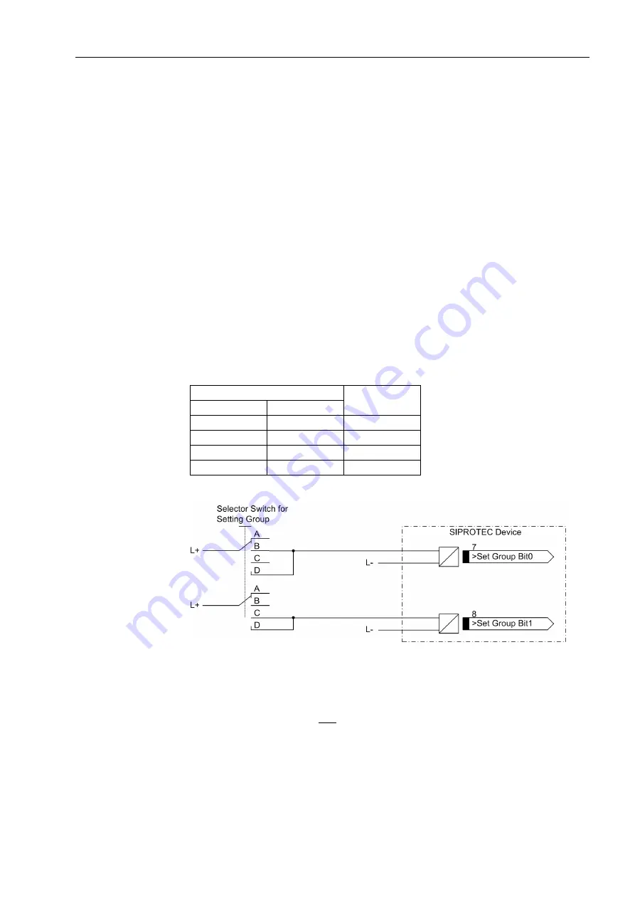
Figure 3-1
Connection diagram (example) for setting group switching with binary inputs
Trip Circuit Super-
vision
It must be noted that two binary inputs or one binary input and one substitute resistor
R must be connected in series. The pick-up threshold of the binary inputs must there-
fore be substantially below half the rated control DC voltage.
If two binary inputs are used for trip circuit supervision, the binary inputs must be iso-
lated, i.e. not communed with each other or with another binary input.
If one binary input is used, a substitute resistor R must be employed (refer to Figure
3-2). The resistor R is inserted into the circuit of the second circuit breaker auxiliary
contact (Aux2), to facilitate the detection of a malfunction also when the first circuit
Binary Input
Active Group
>Set Group Bit0 >Set Group Bit1
No
No
Group A
Yes
No
Group B
No
Yes
Group C
Yes
Yes
Group D
www
. ElectricalPartManuals
. com