
3.1 Mounting and Connections
231
7ST6 Manual
E50417-G1176-C251-A3
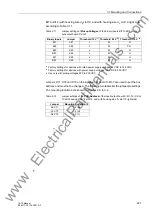
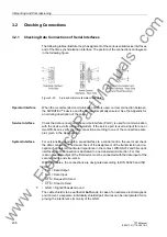
Termination
For bus-capable interfaces a termination is necessary at the bus for each last device,
i.e. terminating resistors must be connected. With the 7ST6 device, this concerns the
variants with RS485 or PROFIBUS interfaces.
The terminating resistors are located on the RS485 or PROFIBUS interface module,
which is on the board C-CPU-2 (No.1 in Figure 3-3 to 3-4), or directly on the PCB of
the processor board C-CPU-2 (see margin heading „Processor Board C-CPU-2“,
Table 3-7).
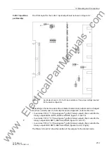
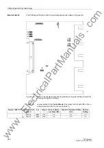
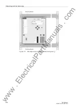
Figure 3-11 shows the C-CPU-2 P.C.B. with the layout of the boards.
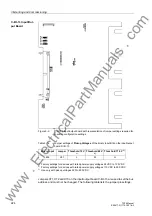
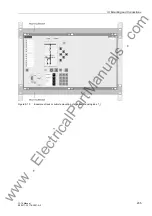
The board with configuration as RS485 interface is shown in Figure 3-13, the module
for the PROFIBUS interface in Figure 3-14.
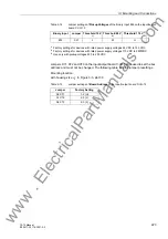
For the configuration of the terminating resistors both jumpers have to be plugged in
the same way.
On delivery the jumpers are set so that the terminating resistors are disconnected.
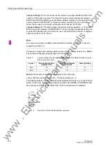
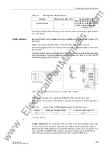
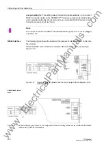
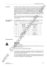
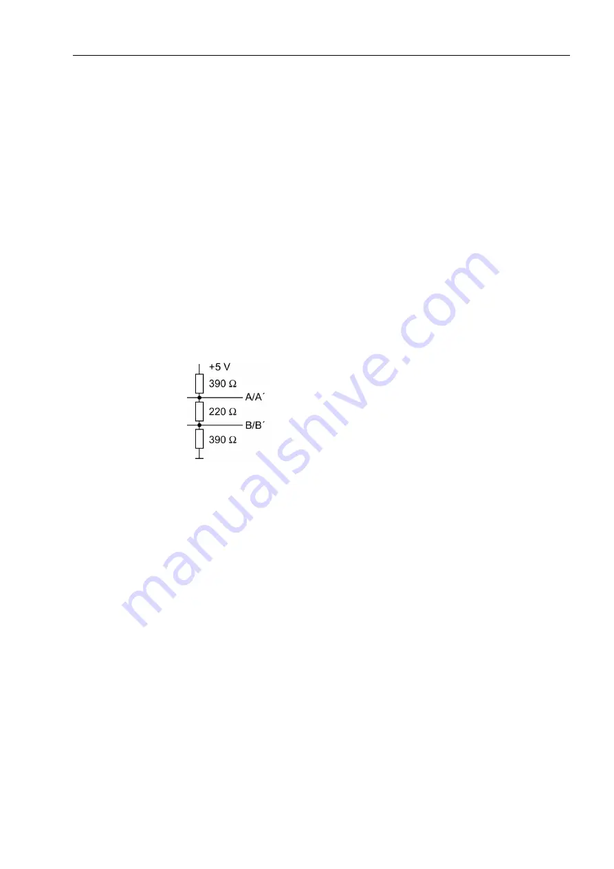
The terminating resistors can also be connected externally (e.g. to the connection
module), see the following figure. In this case, the terminating resistors located on the
RS485 or PROFIBUS interface module or directly on the PCB of the processor board
C-CPU-2 must be de-energized.
Figure 3-15
Termination of the RS485 interface (external)
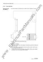
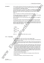
3.1.2.5
Reassembly
The reassembly of the device is carried out in the following steps:
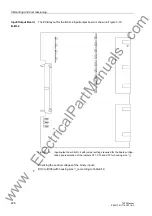
• Insert the boards carefully in the housing. The mounting locations of the boards are
• First plug in the plug connectors of the ribbon cable onto the input/output boards I/O
and then onto the processor board C-CPU-2. Avoid to bend connection pins! Do not
apply force!
• Connect the plug connectors of the ribbon cable between the C-CPU-2 board and
the front panel to the front panel plug connector. These activities are not necessary
if the device has a detached operator panel. Instead of this, the connector of the
ribbon cable connected to the 68-pin connector on the device rear panel must be
plugged on the connector of the processor board C-CPU-2. The 7-pole X16 con-
nector belonging to the ribbon cable must be plugged behind the D-subminiature
female connector. The plugging position is not relevant in this context as the con-
nection is protected against polarity reversal.
• Press the connector latches together.
• Attach the front cover and fix it again to the housing by means of the screws.
• Plug on the caps.
• Re-fasten the interfaces on the rear of the device housing.
www
. ElectricalPartManuals
. com