


3 Mounting and Commissioning
220
7ST6 Manual
E50417-G1176-C251-A3
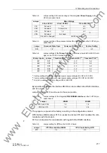
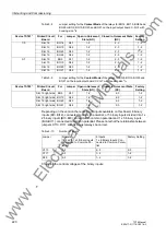
Table 3-8
Jumper setting for the
Contact Mode
of the relays for BO14, BO15, BO25 and
BO26 or BO9, BO10, BO20 and BO21 on the input/output board C-I/O-7 with
housing size
1
/
2
Table 3-9
Jumper setting for the
Contact Mode
of the relays for BO9, BO10, BO20 and
BO21 on the input/output board C-I/O-7 with housing size
1
/
1
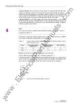
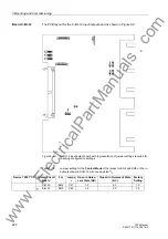
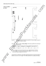
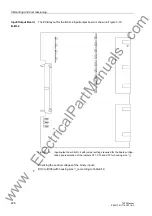
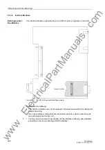
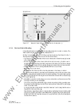
Depending on the version there are 5 or 6 inputs available on this board. 6 binary
inputs (BI7–BI12), connected to common potential, or 5 binary inputs divided into 1 x
2 binary inputs (BI7–BI8), connected to common potential and 1 x 3 binary inputs
(BI9–BI11), connected to common potential. Please note that the relationship between
jumpers X110, X111 and X29 must always be correct.
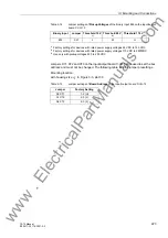
Table 3-10
Number of inputs
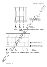
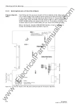
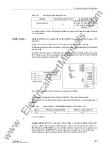
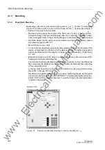
Checking the control voltages of the binary inputs:
Device 7ST61*
Printed Circuit
Board
For
Jumper Open in Quiescent
State (NO)
Closed in Quiescent State
(NC)
Factory
Setting
1/5
Slot 19
BO14
X41
1-2
2-3
1-2
Slot 19
BO15
X42
1-2
2-3
1-2
Slot 19
BO25
X43
1-2
2-3
1-2
Slot 19
BO26
X44
1-2
2-3
1-2
3/7
Slot 19
BO9
X41
1-2
2-3
1-2
Slot 19
BO10
X42
1-2
2-3
1-2
Slot 19
BO20
X43
1-2
2-3
1-2
Slot 19
BO21
X44
1-2
2-3
1-2
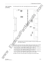
Device 7ST63*
Printed Circuit
Board
For
Jumper Open in Quiescent
State (NO)
Closed in Quiescent State
(NC)
Factory
Setting
Slot 19 right side
BO9
X41
1-2
2-3
1-2
Slot 19 right side BO10
X42
1-2
2-3
1-2
Slot 19 right side BO20
X43
1-2
2-3
1-2
Slot 19 right side BO21
X44
1-2
2-3
1-2
Jumper
5 Inputs
1 x 2 and 1 x 3 Binary Inputs,
Connected to Common Po-
tential
6 Inputs
1 x 6 Binary Inputs, Con-
nected to Common Poten-
tial
Factory Setting
X110
1–2
2–3
2–3
X111
2–3
1–2
1–2
X29
2–3
1–2
1–2
www
. ElectricalPartManuals
. com