


2.2 Distance Protection
67
7ST6 Manual
E50417-G1176-C251-A3
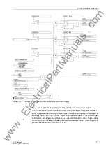
Inrush Blocking
If the protection zone of the device includes power transformers, tripping may be
caused by the inrush effect when switching in transmission lines operating at weak
load or no load.
With such a constellation, you should activate the blocking of the distance protection
by inrush detection. To do so, set under address
2301
Inrush DIS >=Z2
=
YES
. This
blocks the zones Z2 and Z3 in case of detection of an inrush.
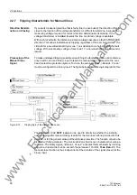
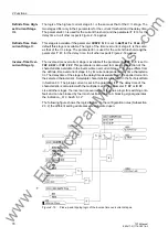
Startup Stages
In highly loaded, long overhead contact lines, the operating currents may be as high
as or even higher than the possible short-circuit currents.
As a result the operating impedances in the backup zones Z2 and Z3 may temporarily
be located within the tripping polygon. The startup stage has the task of distinguishing
between operational events such as startup procedures, and short-circuits.
The zones Z2 and Z3 have each two different grading margins. The grading margins
T2K
(address
1346
) and
T3K
(address
1366
) are activated on detection of a short-
circuit. These grading margins must be set according to the grading coordination
chart.
The grading margins
T2L
(address
1347
) and
T3L
(address
1367
) are activated in
case of an overload. These margins must be set according to the overload carrying
capacity of the overhead contact line.
The distinction between an overload and a short-circuit relies on the fact that in case
of an overload the difference between the phasors of the currently measured current
and of the current measured two cycles ago is much less than in case of a short-circuit.
This current difference is defined by the parameters
di/dt Z2
(address
1343
) and
di/dt Z3
(address
1363
) referred to the rated current.
The change of the value of the current and the voltage are also taken into consider-
ation for the decision. For the release of the grading time TxK, the current must in-
crease and the voltage decrease.
Set this current rise rate to approx. 10% more than the maximum value occurring in
operation. If you do not want to use this criterion for a particular stage, set „
∞
“.
In addition to the current rise rate criterion, voltage dips are used to distinguish
between overloads and short-circuits. The criterion is the difference between the
voltage phasors of the currently measured voltage and the voltage measured two
cycles ago.
For the parameters
du/dt Z2
(address
1344
) and
du/dt Z3
(address
1364
) a value
referred to the rated voltage must be specified. As soon as one of the set thresholds
is exceeded, a short-circuit is detected. Set this voltage dip rate to approx. 10% more
than the maximum value occurring in operation.
The criterion for the voltage dip rate is only activated when the minimum voltages set
in the parameters
Dead VoltThr Z2
(address
1345
) and
Dead VoltThr Z3
(ad-
dress
1365
) are undershot. Set here the maximum possible voltage dip for each
stage in operation, with a safety margin of approx. 10%.
www
. ElectricalPartManuals
. com