

3.3 Commissioning
241
7ST6 Manual
E50417-G1176-C251-A3
WARNING!
Warning of dangers evolving from improper primary tests
Non-observance of the following measure can result in death, personal injury or sub-
stantial property damage.
Primary tests may only be carried out by qualified persons who are familiar with com-
missioning protection systems, with managing power systems and the relevant safety
rules and guidelines (switching, earthing etc.).
3.3.1
Test Mode and Transmission Block
Activation and De-
activation
If the device is connected to a central or main computer system via the SCADA inter-
face, then the information that is transmitted can be influenced. This is only possible
with some of the protocols available (see Table „Protocol-dependent Functions“ in the
Appendix A.6).
If
Test mode
is activated, then a message sent by a SIPROTEC
®
4 device to the main
system has an additional test bit. This bit allows the indication to be recognized as re-
sulting from testing and not an actual fault or power system event. In addition to this,
the user can determine by activating the
transmission block
that no indications at all
are transferred via the system interface during a test operation.
The SIPROTEC
®
4 System Description describes in detail how to activate and deac-
tivate test mode and blocked data transmission (Order No. E50417-H1176-C151).
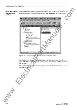
Note that when DIGSI
®
is being used, the program must be in the
Online
operating
mode for the test features to be used.
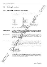
3.3.2
Checking Time Synchronization
If external time synchronization sources are used, the data of the time source (antenna
system, time generator) are checked (see Chapter 4 under „Time Synchronization“).
A correct function (IRIG B, DCF77) is recognized in such a way that 3 minutes after
the startup of the device the clock status is displayed as „synchronized“, accompanied
by the indication „Alarm Clock OFF“.
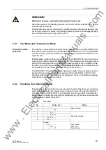
Table 3-24
Time Status
No.
Status Text
Status
1
– – – – – – – –
Synchronized
2
– – – – – – ST
3
– – – – ER – –
Not synchronized
4
– – – – ER ST
5
– – NS ER – –
6
– – NS – – – –
Legend:
– – NS – – – –
– – – – ER – –
– – – – – – ST
Time invalid
Time fault
Summer time
www
. ElectricalPartManuals
. com