


3.1 Mounting and Connections
213
7ST6 Manual
E50417-G1176-C251-A3
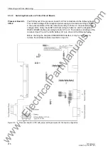
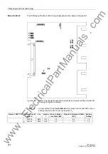
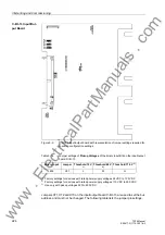
cessor module C-CPU-2 is described in the following sections under „Processor Board
C-CPU-2“ and on the interface modules under „RS485 Interface“ and „PROFIBUS In-
terface“. Both jumpers must be plugged in the same way.
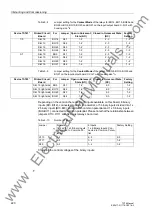
On delivery of the device, the terminating resistors are switched ON.
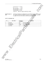
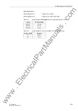
Spare Parts
Spare parts can be the battery for storage of data in the battery-buffered RAM in case
of a power failure, and the internal power supply miniature fuse. Their spatial arrange-
ment is shown in the figure of the processor board. The ratings of the fuse are printed
on the board next to the fuse itself. When exchanging the fuse, please observe the
hints given in the SIPROTEC
®
4 System Description in the chapter „Maintenance“ and
„Corrective Action / Repairs“.
3.1.2.2
Disassembly
Work on the Printed
Circuit Boards
Note
It is assumed for the following steps that the device is not in operation.
Caution!
Caution when changing jumper settings that affect nominal values of the
device:
As a consequence, the order number (MLFB) and the ratings on the nameplate no
longer match the actual device properties.
Where such changes are necessary in exceptional changes, they MUST be marked
clearly and visibly on the device. Self adhesive stickers are available that can be used
as replacement nameplates.
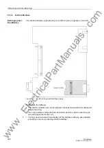
To perform work on the PCB´s, such as checking or rearranging switching elements
or exchanging modules, proceed as follows:
• Prepare area of work: Prepare a surface appropriate to electrostatic sensitive
devices (ESD). In addition to this, the following tools are required:
– Screwdriver with a 5 to 6 mm wide tip,
– Philips screwdriver size 1,
– 5 mm socket or nut driver.
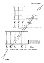
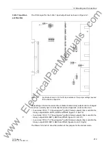
• Unfasten the screw-posts of the D-subminiature connectors on the back panel at
location „A“ and „C“.
• If the device has, in addition to the communication interfaces at locations „A“ and
„C“, interfaces at locations „B“ and „D“, the screws located diagonally to the inter-
faces must be removed.
www
. ElectricalPartManuals
. com