Appendix G Dynamic Brake Unit and Braking Resistor
169
App.H
Time
Output
frequency
Tb
Ta
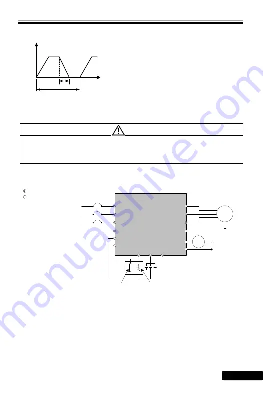
f. Wiring Diagram of External Braking Resistor and Thermal Switch
CAUTION
Strongly recommend to Install the thermal switch for the brake protection to
prevent the brake from any possible damages caused by the overheating on the
braking resistor. Please refer to the figure 1 and 2 as following for the wiring
diagram.
1.) Wiring diagram a
RM6F5
IM
Tc2
Ta2
R/L1
S/L2
T/L3
W/T3
V/T2
PE
U/T1
PR
P
N
Main Circuit Terminal
Control Terminal
PE
R/L1
S/L2
T/L3
MC
X4
(External Fault)
COM
MC
Braking Resistor (option)
Three-phase AC
power source
(single-phase terminal
are R/L1,S/L2)
Thermal Switch
(OHD3-100B)
AC Motor
(Figure 1)
(1) Use the thermal switch to protect the temperature of braking resistor and
generate an external fault signal to the multi-function terminal (X4) to stop the
drive when the braking resistor is overheating and interrupt the connection of
magnet contactor (MC) by output terminals Ta2 / Tc2.
(2) Set the multi-function terminal (X4) to
―-7‖ (External fault).
(3) Set the multi-function terminal (Ta2 / Tc2) to
―-11‖ (Error detection).
Note:
1. %ED (Effective Duty Cycle) = Tb/Ta*100%
(continuous operation time Tb<15 sec).The
definition is shown as above figure.
2. Above wattages of table is defined at 10%ED.
3. 200V series drive or DBU braking activation
voltage is DC 395V
4. 400V series drive or DBU braking activation
voltage is DC 790V
Summary of Contents for RM6F5 series
Page 1: ...AC MOTOR DRIVE Operation Manual RM6F5 series ...
Page 194: ...Notes 194 Notes ...
Page 195: ...Notes 195 Notes ...


