


OmniTek OTR 1001 User Guide, v3.1
C-12
C.3 Video Stream
The OTR 1001 supports a range of possible sources for the video stream to analyse.
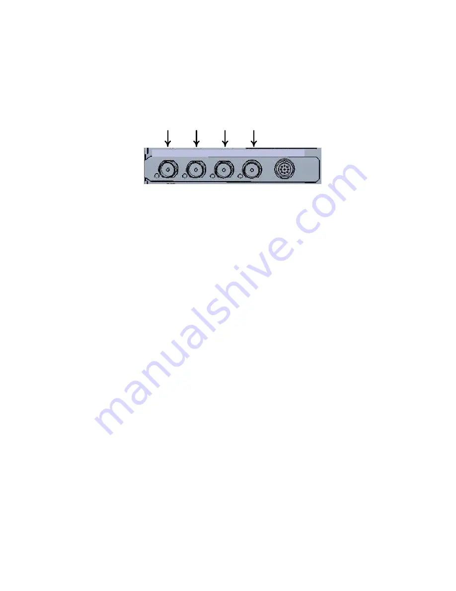
The main option is provided by the two SDI inputs included on the back panel of the OTR 1001.
These are provided by the left-most pair of BNCs of the group of four that appear on the same
card as the Analog connector. Each of these inputs can supply one or more video stream to
analyse.
SDI
Output 2
SDI
Output 1
SDI
Input 2
SDI
Input 1
SDI IN1 SDI IN2 SDI OUT1 SDI OUT2 ANA OUT
Figure C-8:
The SDI Input (and Output) Connectors.
Further inputs are available where the instrument includes a Jitter card. Where the system
includes either the GEN or the GEN_BASIC option, it is also possible to set the OTR 1001 to
analyse the output from its own test signal generator.
Depending on the options installed, the OTR 1001 has the potential to analyse video delivered in
a wide range of standards from the PAL and NTSC SD standards (supported as standard by all
implementations of the OTR 1001), through to HD, 3GA and 3GB standards.
The OTR 1001’s View window typically displays the results of analysing video on one particular
input and, when a different input is selected, all the displays instantly switch to the selected
input. But where one of the Simultaneous Monitoring options is installed, it is possible for two or
more video streams to be monitored at the same time. This is explained in Section O.
Video Stream Selection
Note:
This section describes how to select a video stream to analyse from among those currently
offered. As supplied, the system is configured to just offer video from the two SDI inputs. How to
configure the OTR 1001 to offer the input from an installed Jitter card is explained in Section T
(System Configuration). Similar steps may also be used to configure the OTR 1001 to analyse the
output from the built-in generator, though there is the alternative of using a cable to feed the
generated video from an SDI output to one of the SDI inputs.
Once the OTR 1001 is suitably configured, the steps given here can be used to select the input
you require.
The OTR 1001 maintains a list of the input streams that are currently available for analysis in its
Inputs toolbar. Precise details of the different services to the inputs are given on the
Video
Inputs
page of the Config window (see Section T.4).
Note:
References to stream 2 (where
shown) refer to the second video stream that is offered by 3G Level B Dual-stream video. Other
video standards only offer a single video stream on any input.
Selecting the input that is analysed is ultimately a matter of picking the required input from
Inputs toolbar. However, it can also be picked out by giving its Input number, which corresponds
to its position in the Inputs toolbar (starting with Input 1 at the top). Alternatively, where a
mouse and keyboard are fitted to the OTR, the input to be analysed in a particular tile can be
selected by dragging the relevant Picture icon on the Status Bar to the tile.
Summary of Contents for OTR 1001
Page 1: ...Advanced Measurement Technology OTR 1001 User Guide Software Version 3 1 October 2013...
Page 28: ...OmniTek OTR 1001 User Guide v3 1a A 16...
Page 52: ...OmniTek OTR 1001 User Guide v3 1 B 24...
Page 96: ...OmniTek OTR 1001 User Guide v3 1a E 24...
Page 116: ...OmniTek OTR 1001 User Guide v3 1 G 6...
Page 124: ...OmniTek OTR 1001 User Guide v3 1 H 8...
Page 184: ...OmniTek OTR 1001 User Guide v3 1 J 22...
Page 238: ...OmniTek OTR 1001 User Guide v3 1 M 14...
Page 250: ...OmniTek OTR 1001 User Guide v3 1 N 12...
Page 254: ...O 4 OmniTek OTR 1001 User Guide v3 1...
Page 292: ...Q 26 OmniTek OTR 1001 User Guide v3 1...
Page 326: ...OmniTek OTR 1001 User Guide v3 1a S 26...
Page 358: ...OmniTek OTR1001 User Guide v3 1 U 12...
Page 364: ...OmniTek OTR 1001 User Guide v3 1 V 6...
Page 379: ...OmniTek OTR 1001 User Guide v3 1 I 15 Example XML Statements Example Result...
Page 386: ...OmniTek OTR 1001 User Guide v3 1 II 6...
Page 389: ...OmniTek OTR 1001 User Guide v3 1...


