Chapter 4
General-Purpose Counter/Timer
©
National Instruments Corporation
4-35
DAQ-STC Technical Reference Manual
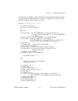
Function
Read_Gi_HW_Save_Registers
{
Declare variables
save=0;
/*Read from the AI_Status_1_Register to check the G0_Gate_Interrupt_St or
read from the AO_Status_1_Register to check the G1_Gate_Interrupt_St.
If the status bit is set, read the hardware save registers (24 bit value). */
if (Gi_Gate_Interrupt_St)
save = Gi_HW_Save_Registers;
}
4.6.1.15 Enabling the General Purpose Counter/Timer Output Pin
The output pin for each general purpose counter/timer must be enabled before it can be used.
This is required for applications such as single or contiuous pulse generation.
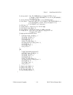
Function
Enable_Gi_Out
{
GPFO_i_Output_Enable=1;
GPFO_i_Output_Select=0;
}
4.6.2 Bitfield Descriptions
Bits in the register bit maps are organized into bitfields. A bitfield can contain one or more
bits. Only bits with contiguous locations within a register can belong to a bitfield. The high
and low pairs of load and save registers for 24-bit counters are also treated as bitfields. The
GPCT-related bitfields are described below. Not all bitfields referred to in section
, are listed here. To locate a particular bitfield description within
this manual, refer to Appendix B,
.
G
i_Analog_Trigger_Reset
i = 0
bit: 3
type: Strobe
in: G0_Command_Register
address: 6
i = 1
bit: 3
type: Strobe
in: G1_Command_Register
address: 7
This bit clears the hysteresis registers in the analog trigger circuit. Set this bit to 1 at the time
you arm general-purpose counter i if you want to use analog triggering in hysteresis mode for
any general-purpose counter i input signal. Before setting this bit to 1, make sure that the
analog trigger is not being used by any other part of the DAQ-STC. You should not set this
bit to 1 in any other case. This bit is cleared automatically.

