Chapter 2
Analog Input Timing/Control
DAQ-STC Technical Reference Manual
2-90
©
National Instruments Corporation
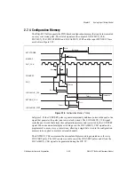
The actual signal timing parameters remain the same whether or not the DIV counter is being
used. The EXTSTROBE signal is intended to be used in conjunction with the digital I/O lines
to write data to an external multiplexer but can be used as a general strobe signal.
The numbers in parentheses refer to the number of clock periods that will occur at the
minimum and maximum delays, because those parameters are clock-edge driven with
possible additional gate delays.
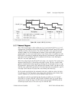
The trailing edge of LOCALMUX_CLK should be used to latch the new configuration
information, which in general should not change until the input signal has been sampled. The
LOCALMUX_CLK signal is asserted by the leading edge of CONVERT and is held for either
two or four output clock edges, regardless of polarity, and then until the active edge of SOC
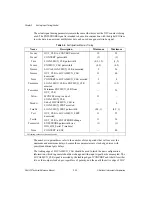
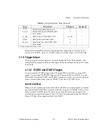
Table 2-4.
Configuration Memory Timing
Name
Description
Minimum
Maximum
Tcconv
OUT_CLK to CONVERT asserted
19
58
Tsconv
CONVERT pulsewidth
(1)
(1)
Tmx
LOCALMUX_CLK pulsewidth
(0.5, 1.5)
(1, 2)
Texmx
EXTMUX_CLK pulsewidth
(4.5)
(4.5)
Tsocmx
SOC to LOCALMUX_CLK deasserted
9
26
Toscmx
OUT_CLK to LOCALMUX_CLK
deasserted
13
40
Tcmx
CONVERT to LOCALMUX_CLK asserted
3
8
Tmxexmx
LOCALMUX_CLK to EXTMUX_CLK
asserted
(1)
(1.5)
Toscexmx
Minimum EXTMUX_CLK from
OUT_CLK
—
36
Tefset
MUXFEF setup to end of
LOCALMUX_CLK
21
—
Tmxdrt
End of LOCALMUX_CLK to
LOCALMUX_FFRT asserted
—
0
Tmxfrt
LOCALMUX_FFRT pulsewidth
(0.5, 1)
(0.5, 1)
Tcrt
OUT_CLK to LOCALMUX_FFRT
deasserted
11
35
Tcstrb
OUT_CLK to EXTSTROBE change
11
36
Texmxstrb
EXTSTROBE pulsewidth (see
DIO_HW_Serial_Timebase)
(1)
(1)
Tcsoc
CONVERT to SOC
—
40
All timing values are in nanoseconds.


