Chapter 3
Analog Output Timing/Control
DAQ-STC Technical Reference Manual
3-114
©
National Instruments Corporation
3.8.2 Trigger Selection and Conditioning
The signal routing block selects the counter clocks, trigger signals, and gate signals from the
default timebases. The routing logic for the UI_SRC, UI2_SRC, and BC_SRC signals is a
20-to-1 multiplexer followed by an exclusive OR gate for polarity selection. The routing logic
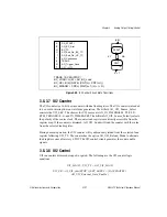
for the trigger signal START1 has additional controls for edge detection and synchronization,
as shown in Figure 3-35. When synchronization is selected, START1 is synchronized to both
UI_SRC and BC_SRC.
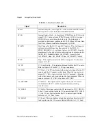
UI2_CE
UI2 Count Enable—This signal enables and disables the UI2 counter.
Refer to section
, for the UI2_CE equations.
UI2_CLK
UI2 Clock—The UI2 clock signal is the actual clock for the UI2
counter and the UI2 control logic. When the counter is not armed,
UI2_CLK is the write strobe for AO_Command_1_Register, so that
the counter can be loaded using the load command. When the counter
is armed, UI2_CLK is the same as UI2_SRC.
UI2_LOAD
UI2 Load—This signal pulses to load the value from the selected UI2
load register into the UI2 counter. Related bitfields: AO_UI2_Load.
UI2_LOAD_SRC
UI2 Load Source—This signal determines which load register, A or
B, the UI2 counter will use on the next reload. The initial UI2 load
source is set using AO_UI2_Initial_Load_Source. The UI2 control
logic updates UI2_LOAD_SRC while the DAQ-STC is counting.
The current load source depends on the counter state and the selected
reload mode. Related bitfields: AO_UI2_Initial_Load_Source,
AO_UI2_Next_Load_Source_St, AO_UI2_Reload_Mode.
UI2_SRC
UI2 Source—The UI2 source is the timebase for the UI2 counter. It
is software selectable from AO_IN_TIMEBASE1, IN_TIMEBASE2,
the G_TC signal from general-purpose counter 0 or 1, PFI<0..9>, and
RTSI_TRIGGER<0..6>. Related bitfields: AO_UI2_Source_Select.
UI2_TC
Secondary Update Interval TC—The UI2_TC signal is the
independent secondary update interval clock.
Table 3-6.
Internal Signals (Continued)
Signal
Description


