Chapter 4
General-Purpose Counter/Timer
©
National Instruments Corporation
4-49
DAQ-STC Technical Reference Manual
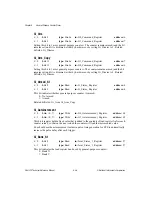
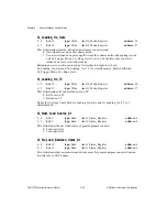
G
i_Synchronized_Gate
i = 0
bit: 8
type: Write
in: G0_Command_Register
address: 6
i = 1
bit: 8
type: Write
in: G1_Command_Register
address: 7
This bit enables gate synchronization to the source:
0: Disabled.
1: Enabled.
You should normally set this bit to 1. You can set this bit to 0 if you know that the gate signal
is synchronized to the source signal.
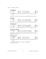
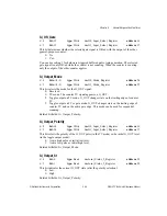
G
i_TC_Error_Confirm
i = 0
bit: 6
type: Strobe
in: Interrupt_A_Ack_Register
address: 2
i = 1
bit: 2
type: Strobe
in: Interrupt_B_Ack_Register
address: 3
Setting this bit to 1 clears Gi_TC_Error_St. This bit is cleared automatically. Related
bitfields: Gi_TC_Error_St.
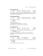
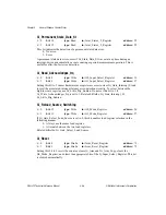
G
i_TC_Error_St
i = 0
bit: 12
type: Read
in: G_Status_Register
address: 4
i = 1
bit: 13
type: Read
in: G_Status_Register
address: 4
This bit indicates the detection of a TC latency error:
0: No.
1: Yes.
A TC latency error is detected if Gi_TC_Interrupt_Ack is not set between two counter TCs.
This allows you to detect large interrupt latencies and potential problems associated with
them. To clear this bit, set Gi_TC_Error_Confirm to 1. Related bitfields:
Gi_TC_Interrupt_Ack, Gi_TC_Error_Confirm.
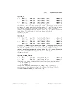
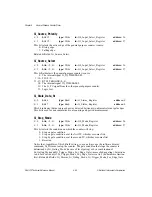
G
i_TC_Interrupt_Ack
i = 0
bit: 14
type: Strobe
in: Interrupt_A_Ack_Register
address: 2
i = 1
bit: 14
type: Strobe
in: Interrupt_B_Ack_Register
address: 3
Setting this bit to 1 clears Gi_TC_St and acknowledges the TC interrupt request (in either
interrupt bank) if the TC interrupt is enabled. This bit is cleared automatically. Related
bitfields: Gi_TC_St.


