Chapter 3
Analog Output Timing/Control
DAQ-STC Technical Reference Manual
3-60
©
National Instruments Corporation
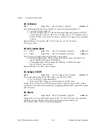
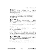
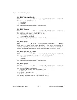
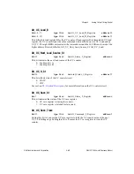
AO_Number_Of_DAC_Packages
bit: 14
type: Write
in: AO_Personal_Register
address: 78
This bit selects the DAC mode:
0: Dual-DAC mode.
1: Single-DAC mode.
The pins DACWR<0..1> pulse on each TMRDACWR and CPUDACWR. In the dual-DAC
mode, DACWR0 pulses on every write and DACWR1 is not used. In the single-DAC mode,
DACWR0 pulses when a write occurs to an even channel and DACWR1 pulses when a write
occurs to an odd channel. If you are using the DAQ-STC on a device with two DACs in
individual packages, set this bit to 1. When you make this selection, you can use pins
DACWR0 and DACWR1. In all other cases, set this bit to 0. When you choose this option,
you should use pin DACWR0 only. Refer to section
, for more
information on DAC modes.
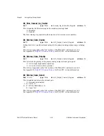
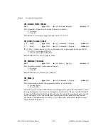
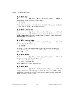
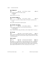
AO_Output_Divide_By_2
bit: 5
type: Write
in: Clock_and_FOUT_Register
address: 56
This bit determines the frequency of the internal timebase AO_OUT_TIMEBASE:
0: Same as IN_TIMEBASE.
1: IN_TIMEBASE divided by 2.
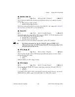
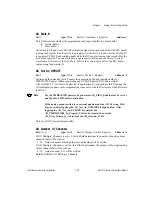
AO_Overrun_St
bit: 9
type: Read
in: AO_Status_1_Register
address: 3
This bit indicates the detection of an overrun error:
0: No error.
1: Error.
An overrun error occurs when an UPDATE command is issued to a DAC that was not loaded
with data. This bit can be cleared by setting AO_Error_Interrupt_Ack to 1. Related bitfields:
AO_Error_Interrupt_Ack.
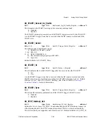
Note
This bit may incorrectly indicate that an error occurred after the end of a
waveform generation sequence if there is no more data in the buffer. You can
avoid this false error by transferring one more point of data to the board than the
waveform generation requires.
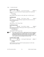
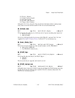
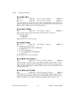
AO_Reset
bit: 1
type: Strobe
in: Joint_Reset_Register
address: 72
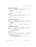
Setting this bit to 1 resets the following registers to their power-on state:
AO_Command_1_Register
AO_Command_2_Register
AO_Interrupt_Control_Register
AO_Mode_1_Register
AO_Mode_2_Register


