Chapter 10
Miscellaneous Functions
©
National Instruments Corporation
10-13
DAQ-STC Technical Reference Manual
Analog_Trigger_Enable
bit: 3
type: Write
in: Analog_Trigger_Etc_Register
address: 61
This bit enables the analog trigger circuitry:
0: Disabled.
1: Enabled.
When the analog trigger circuit is enabled, the analog trigger signal takes over the PFI0 slot
in the PFI selectors.
Analog_Trigger_Mode
bits: <0..2>
type: Write
in: Analog_Trigger_Etc_Register
address: 61
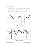
This bit selects the analog trigger mode of operation if the analog trigger circuitry is enabled:
0: Low window.
1: High window.
2: Middle window.
4: High hysteresis.
6: Low hysteresis.
Related bitfield: Analog_Trigger_Enable.
Clock_To_Board
bit: 8
type: Write
in: Clock_and_FOUT_Register
address: 56
This bit enables the IN_TIMEBASE to feedback or feedthrough to the board through the
OUTBRD_OSC pin:
0: Disabled.
1: Enabled.
Clock_To_Board_Divide_By_2
bit: 9
type: Write
in: Clock_and_FOUT_Register
address: 56
If the Clock_To_Board bit is set to 1, this bit selects whether IN_TIMEBASE (as selected by
the RTSI_Clock_Mode bitfield) will be divided by 2 when it is fed to the board through the
OUTBRD_OSC pin.
0: Do not divide by 2.
1: Divide by 2.
FOUT_Divider
bits: <0..3>
type: Write
in: Clock_and_FOUT_Register
address: 56
This bit selects the divide ratio for the FOUT output signal:
0: Divide by 16. FOUT = FOUT_TIMEBASE divided by 16.
1-15: Divide by 1-15. FOUT = FOUT_TIMEBASE divided by 1-15.
Related bitfields: FOUT_Timebase_Select, FOUT_Enable.

