Chapter 2
Analog Input Timing/Control
©
National Instruments Corporation
2-119
DAQ-STC Technical Reference Manual
2.8.2 Trigger Selection and Conditioning
The signal routing block selects the counter clocks, trigger signals, and gate signals from the
default timebases (AI_IN_TIMEBASE1 and IN_TIMEBASE2), internal counter outputs,
software strobes, and the programmable function timing inputs. The routing logic for the
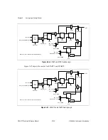
SI_SRC and SCLK signals is a 20-to-1 multiplexer followed by an exclusive OR gate for
polarity selection. The routing logic for the trigger signals START and STOP has additional
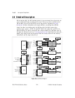
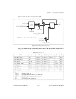
controls for edge detection and synchronization as shown in Figure 2-46.
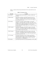
STOP
Stop—This signal performs two functions. In the start/stop mode, it
halts CONVERT generation until the next START. This is accomplished
by stopping the SI2 counter at the next sample pulse if an internal
CONVERT is used or by clearing the STST_GATE at the next sample
pulse if an external CONVERT is used. The STOP signal also serves as
an end of scan (last channel) signal and is used by the SC counter to
count scans. Related bitfields: AI_STOP_Select, AI_STOP_Pulse,
AI_STOP_Edge, AI_STOP_Sync.
STST_GATE
Start/Stop Gate—This signal is used for conditioning the external
CONVERT so that CONVERT passes through only between the
assertion of START and the assertion of STOP. STST_GATE is set by
the assertion of START after the SC counter has been armed and
triggered and is cleared by the assertion of STOP or when the SC
counter returns to the WAIT1 state. Related bitfields:
AI_Start_Stop_Gate_Enable, AI_Start_Stop_Gate_St.
Table 2-9.
Internal Signals (Continued)
Signal
Description


