Chapter 2
Analog Input Timing/Control
DAQ-STC Technical Reference Manual
2-124
©
National Instruments Corporation
2.8.3.1 SC Counter
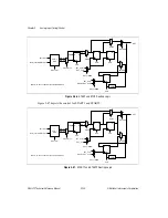
The SC counter is a 24-bit down counter with dual-load registers and output save latch. The
SC counter is used to count scans. When you select internal CONVERT, the SC counter
source is equal to SI_SRC. In this mode the SC counter increments on SI2_TC AND STOP.
When you select external CONVERT, the SC counter source is SCLK. In this mode the SC
counter increments on every STOP.
The counter load registers are directly accessible (in write mode) from the register map. If the
counter is disarmed, AI_SC_Load will load the counter with the value from the selected load
register. The AI_SC_Write_Switch option allows the load register writes to be directed to the
inactive load register.
During normal operation, the SC counter will synchronously reload from the selected load
register following SC_TC. Several options allow the SC counter to change the selected load
register under various conditions. The options are to switch load registers on every SC_TC
(AI_SC_Reload_Mode) and to switch load registers on the next SC_TC
(AI_SC_Switch_Load_On_TC). The SC control circuit (discussed below) generates the
count enable signals.
The SC save register latch signal asserts after a rising and then a falling edge of SC_SRC
following a 1 being written to AI_SC_Save. The SC save register latch signal deasserts after
a rising and then a falling edge of SC_SRC following a 0 being written to AI_SC_Save.
2.8.3.2 SC Control
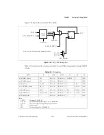
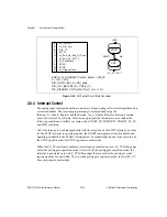
The SC counter is controlled by a circuit whose state transitions are shown in Figure 2-49.
The SC counter control circuit has four states: WAIT1, PCNT, WAIT2, and CNT. The bitfield
AI_Pre_Trigger determines the sequence of the control circuit. When AI_Pre_Trigger is low,
the counter simply counts until the scan requirement is fulfilled. When AI_Pre_Trigger is
high, the counter first satisfies the pretrigger scan requirement before fulfilling the posttrigger
scan requirement.
On power up, the counter begins in WAIT1 and remains there until the counter is armed and
a START1 pulse is received. If AI_Pre_Trigger is low, the counter moves directly to the CNT
state. If AI_Pre_Trigger is high, the counter moves to PCNT and remains counting until
reaching SC_TC (fulfilling the pretrigger requirement). The control circuit then transitions to
WAIT2 to wait for the START2 signal. When START2 is received, the control circuit
transitions to CNT, and the counter continues to count scans until SC_TC. When the counting
is complete, SC_TC causes the control circuit to return to WAIT1.
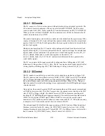
The internal signal SCKG affects the count operation of the SC counter. When the internal
timebase is selected for the SC source (AI_CONVERT_Source_Select is set to 0), SCKG
becomes the sample interval counter TC signal (SI2_TC). If a different source is selected for
the SC counter (AI_CONVERT_Source_Select is not set to 0) SCKG = 1.


