Chapter 3
Analog Output Timing/Control
©
National Instruments Corporation
3-71
DAQ-STC Technical Reference Manual
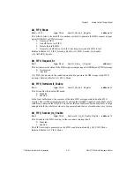
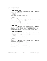
AO_UC_TC_Interrupt_Enable
bit: 6
type: Write
in: Interrupt_B_Enable_Register
address: 75
This bit enables the UC_TC interrupt:
0: Disabled.
1: Enabled.
UC_TC interrupts are generated on the leading edge of UC_TC.
AO_UC_TC_Second_Irq_Enable
bit: 6
type: Write
in: Second_Irq_B_Enable_Register
address: 76
This bit enables the UC_TC interrupt in the secondary interrupt bank:
0: Disabled.
1: Enabled.
UC_TC interrupts are generated at the leading edge of UC_TC.
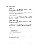
AO_UC_TC_St
bit: 6
type: Read
in: AO_Status_1_Register
address: 3
This bit indicates whether the UC counter has reached TC:
0: No
1: Yes.
To clear this bit, set AO_UC_TC_Interrupt_Ack to 1. Related bitfields:
AO_UC_TC_Interrupt_Ack. Refer to Table 8-2,
, for more
information.
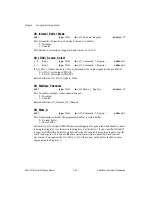
AO_UC_Write_Switch
bit: 10
type: Write
in: AO_Mode_2_Register
address: 39
This bit enables the write switch feature of the UC load registers. Writes to UC load register
A are:
0: Unconditionally directed to UC load register A.
1: Directed to the inactive UC load register.
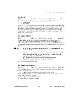
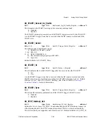
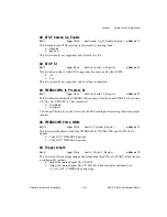
AO_UI_Arm
bit: 10
type: Strobe
in: AO_Command_1_Register
address: 9
Setting this bit to 1 arms the UI counter. The counter remains armed, and the bit remains set,
until it is disarmed either by hardware or by setting AO_Disarm to 1. Related bitfields:
AO_UI_Arm, AO_Disarm.

