Chapter 3
Analog Output Timing/Control
©
National Instruments Corporation
3-121
DAQ-STC Technical Reference Manual
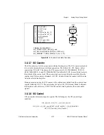
Figure 3-39.
BC Control Circuit State Transitions
3.8.3.7 UI2 Counter
The UI2 counter is a 16-bit down counter with dual load registers. The UI2 counter is intended
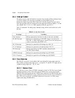
to be used in interrupt-driven waveform generation. The bitfield AO_UI2_Source_Select
controls the UI2_SRC. The choices for UI2 source are AO_IN_TIMEBASE1, PFI<0..9>,
RTSI_TRIGGER<0..6> and IN_TIMEBASE2. The bitfield AO_UI2_Source_Polarity selects
the polarity of the source clock. The counter load registers are directly accessible from the
register map. If the counter is disarmed, AO_UI2_Load will load the counter with the value
from the selected load register.
During normal operation, the UI2 counter will synchronously reload from the selected load
register following UI2_TC. The counter has the option AO_UI2_Reload_Mode to alternate
load registers once after every STOP. The UI2 control circuit generates the count enable
signals.
3.8.3.8 UI2 Control
UI2 runs unless disarmed, stopped, or gated. The following are the UI2 counter logic
equations.
UI2_LOAD = AO_UI2_LOAD
UI2_CE = AI_UI2_Arm(STOP’) (EXT (DA_SFGATE2’)
AO_UI2_External_Gate_Enable’)
A
B
G
H
I
J
K
DA_START1
AO_BC_Arm
BC_TC
AO_End_On_BC_TC
AO_End_On_UC_TC
AO_Continuous
BC_LOAD = G(K) + AO_BC_Load
BC_CE = B(K) (GATE) (CNT(n) + CNT(n+1))
BC_DISARM = CNT(n) WAIT(n+1) (H + I + N)
(AB)'
WAIT
CNT
AB
KT'
K' + T
N
T
AO_Trigger_Once
G'H' + H'I'J
TRANS
TRANS = SCKG(STOP)


