Chapter 3
Analog Output Timing/Control
DAQ-STC Technical Reference Manual
3-100
©
National Instruments Corporation
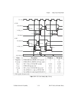
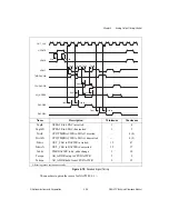
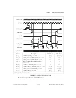
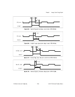
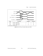
The numbers in square brackets indicate the number of clock periods that occur at the
minimum and maximum delays, because those parameters are clock-edge driven with
possible additional gate delays.
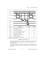
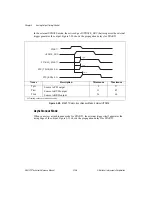
The UPDATE signal still performs the updating of the DACs, as before. The TMRDACWR
signal is now used as a DMA request, indicating that new data is needed for the analog output.
The CPUDACWR signal is used to actually write the DMA data to the DACs. The
TMRDACWR signal will remain asserted until the completion of the last CPUDACWR. The
AOFFF input is the DMA acknowledge, indicating that the DMA data is ready for the write.
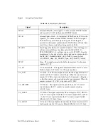
The CPUDACREQ input is still used to provide CPU access to DACs. The CHRDY_OUT
signal acts as before, and extends the bus cycle to the appropriate length during both of CPU
or DMA accesses. The AO_ADDR<0..3> lines still indicate the destination DAC but change
on the CPUDACWR signal instead of the TMRDACWR signal as before. The bus address
lines A<0..3> will still pass through to the AO_ADDR<0..3> lines during a CPU access.

