Chapter 3
Analog Output Timing/Control
DAQ-STC Technical Reference Manual
3-56
©
National Instruments Corporation
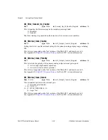
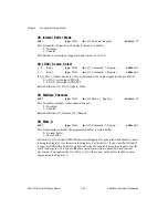
AO_FIFO_Flags_Polarity
bit: 11
type: Write
in: AO_Personal_Register
address: 78
This bit selects the polarity of the data FIFO flags (input signals AOFFF, AOFHF, and
AOFEF):
0: Active low.
1: Active high.
Related bitfields: AO_FIFO_Full_St, AO_FIFO_Half_Full_St, AO_FIFO_Empty_St.
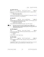
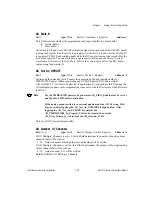
AO_FIFO_Full_St
bit: 14
type: Read
in: AO_Status_1_Register
address: 3
This bit reflects the state of the AOFFF input signal (after the polarity selection), which
indicates the data FIFO status:
0: Not full.
1: Full.
Related bitfields: AO_FIFO_Flags_Polarity.
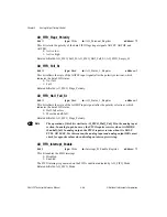
AO_FIFO_Half_Full_St
bit: 13
type: Read
in: AO_Status_1_Register
address: 3
This bit reflects the state of the AOFHF input signal (after the polarity selection), which
indicates the data FIFO status:
0: Half-full or less.
1: More than half-full.
Related bitfields: AO_FIFO_Flags_Polarity.
Note
The operation of this bit is similar to AI_FIFO_Half_Full_St in the analog input
section. In analog input, however, the FIFO requires service when it is MORE
than half-full. In analog output, the FIFO requires service when it is HALF
FULL OR LESS. For this reason, the analog input and analog output ISRs must
check for opposite values when deciding on interrupt servicing.
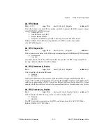
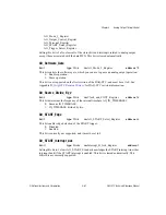
AO_FIFO_Interrupt_Enable
bit: 8
type: Write
in: Interrupt_B_Enable_Register
address: 75
This bit enables the FIFO interrupt:
0: Disabled.
1: Enabled.
The FIFO interrupt is generated on the FIFO condition indicated by AO_FIFO_Mode.
Related bitfields: AO_FIFO_Mode.

