Chapter 3
Analog Output Timing/Control
©
National Instruments Corporation
3-35
DAQ-STC Technical Reference Manual
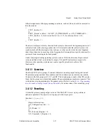
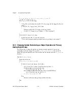
If (
AO_UI_Next_Load_Source_St
is 1) then
{
AO_UI_Load_A = number of clocks between updates - 1;
If (change update rate immediately) then
AO_UI_Switch_Load_On_TC = 1;
Else if (change update rate at the end of the current MISB) then
AO_UI_Switch_Load_On_BC_TC = 1;
ao_last_load_register
= A;
}
Else
Inform user that rate change is impossible at this time;
}
End critical section;
}
To change the update rate immediately, you must perform at least one update using the
previous update interval before a change is possible. The other option is to change the update
rate at the end of the current MISB.
3.6.4 Master/Slave Operation Considerations for Primary Analog
Output Group
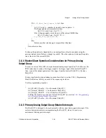
You can use several DAQ-STCs for synchronized analog output operation. To do this, use the
RTSI connection to connect the trigger signal to the trigger input of the master DAQ-STC.
Also, connect the output equivalent of the trigger from the master DAQ-STC to the slave
DAQ-STCs.
You must perform the programming sequence described in section 10.8.1, Programming
Clock Distribution, before you execute the sequence given here.
Use this programming sequence:
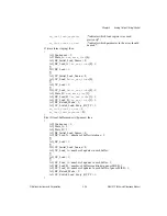
{
AO_START1_Disable = 1 for the master DAQ-STC;
AO_Delayed_START1 = 1 for the master DAQ-STC;
AO_Delayed_START1 = 0 for all the slave DAQ-STCs;
Perform the usual set-up sequence for each DAQ-STC (see section
for a Primary Analog Output Operation
);
AO_START1_Disable = 0 for the master DAQ-STC;
}
3.6.5 Primary Analog Output Group-Related Interrupts
The DAQ-STC is designed to be used primarily with a system that supports interrupts. This
section contains instructions on programming the DAQ-STC when it is used in an
environment that supports interrupts.

