Chapter 4
General-Purpose Counter/Timer
DAQ-STC Technical Reference Manual
4-52
©
National Instruments Corporation
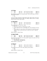
GPFO_0_Output_Select
bits: <11..13>
type: Write
in: Analog_Trigger_Etc_Register
address: 61
This bit selects the output source for the G_OUT0/RTSI_IO bidirectional pin if the pin is
configured for output:
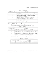
0: General-purpose counter 0 output (G_OUT).
1–7: Signal from the RTSI trigger line <0..6>.
Related bitfields: GPFO_0_OUTPUT_Enable.
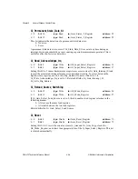
GPFO_1_Output_Enable
bit: 15
type: Write
in: Analog_Trigger_Etc_Register
address: 61
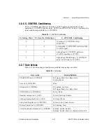
This bit enables the G_OUT1/DIV_TC_OUT output signal:
0: Disabled.
1: Enabled.
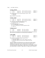
GPFO_1_Output_Select
bit: 7
type: Write
in: Analog_Trigger_Etc_Register
address: 61
This bit selects the output source for the G_OUT1/DIV_TC_OUT output signal, if enabled
for output:
0: General-purpose counter 1 output (G_OUT).
1: The internal analog input signal DIV_TC.
Related bitfields: GPFO_1_OUTPUT_Enable.
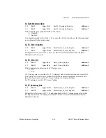
G_Source_Divide_By_2
bit: 10
type: Write
in: Clock_and_FOUT_Register
address: 56
This bit determines the frequency of the internal timebase G_IN_TIMEBASE:
0: Same as IN_TIMEBASE.
1: IN_TIMEBASE divided by 2.

