Chapter 3
Analog Output Timing/Control
©
National Instruments Corporation
3-119
DAQ-STC Technical Reference Manual
The options are to switch load registers on the next BC_TC and switch load registers on the
next UC_TC. The UC control circuit generates the count enable signals.
The UC save register latch signal asserts after a rising, then a falling edge of BC_SRC
following a 1 being written to AO_UC_Save_Trace. The UC save register latch signal
deasserts after a rising, then a falling edge of BC_SRC following a zero being written to
AO_UC_Save_Trace.
3.8.3.4 UC Control
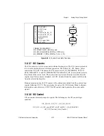
The UC counter is controlled by a circuit whose state transitions are shown in Figure 3-38.
The UC counter control circuit has two states—WAIT and CNT. On power up, the control
circuit begins and remains in the WAIT state until the counter is armed and a START1 pulse
is received. When these two events occur, the control circuit moves to the CNT state and the
counter begins counting. On UC_TC, the control circuit either remains in CNT or returns to
the WAIT state depending on the signals STOP, AO_End_On_BC_TC,
AO_End_On_UC_TC, BC_TC, and AO_Continuous.
For continuous acquisition modes, the UC counter control circuit can return to the WAIT state
based on the software strobes AO_End_On_BC_TC and AO_End_On_UC_TC. Also, the UC
counter normally remains armed and retriggerable at the end of a scan sequence. The UC
counter has the option AO_Trigger_Once to disarm itself when returning to the WAIT state.
Figure 3-38.
UC Control Circuit State Transitions
A
B
E
G
H
I
J
K
M
DA_START1
AO_UC_Arm
UC_TC
BC_TC
AO_End_On_BC_TC
AO_End_On_UC_TC
AO_Continuous
SCKG
STOP
UC_LOAD = EK + AO_UC_Load
UC_CE = BK (EX INT_SCLK_SEL) (CNT(n) + CNT(n+1))
UC_DISARM = (H + I + N) CNT(n) WAIT(n+1)
(AB)'
WAIT
CNT
AB
EMKT'
E' + K' + M' + T
N
T
AO_Trigger_Once
G'H' + H'I'J

