Chapter 5
Programmable Function Inputs
DAQ-STC Technical Reference Manual
5-6
©
National Instruments Corporation
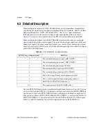
case 2:
BD_2_Pin_Dir = 0 (input) or 1 (output);
break;
case 3:
BD_3_Pin_Dir = 0 (input) or 1 (output);
break;
case 4:
BD_4_Pin_Dir = 0 (input) or 1 (output);
break;
case 5:
BD_5_Pin_Dir = 0 (input) or 1 (output);
break;
case 6:
BD_6_Pin_Dir = 0 (input) or 1 (output);
break;
case 7:
BD_7_Pin_Dir = 0 (input) or 1 (output);
If (BD_7_Pin_Dir is 1) then
AI_START_Output_Select = 0 (output AD START) or
1 (output AD SCAN_IN_PROG);
break;
case 8:
BD_8_Pin_Dir = 0 (input) or 1 (output);
break;
case 9:
BD_9_Pin_Dir = 0 (input) or 1 (output);
break;
}
}
Warning
You must be very careful when programming bidirectional pins for output. If an
external signal is driving a bidirectional pin and you configure the pin for output,
you may cause physical damage to the DAQ-STC, the external circuitry, or both.
5.4.2 Bitfield Descriptions
Bits in the register bit maps are organized into bitfields. A bitfield can contain one or more
bits. Only bits with contiguous locations within a register can belong to a bitfield. The high
and low pairs of load and save registers for 24-bit counters are also treated as bitfields.
The PFI-related bitfields are described below. Not all bitfields referred to in section
, are listed here. To locate a particular bitfield description within
this manual, refer to Appendix B,
.


