Chapter 2
Analog Input Timing/Control
©
National Instruments Corporation
2-123
DAQ-STC Technical Reference Manual
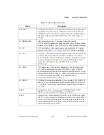
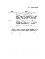
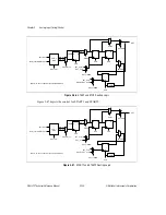
STOP is used to end the conversion pulse sequence when the number of channels has been
reached. For low-end applications, the DIV counter generates STOP. For high-end
applications, the configuration FIFO provides STOP. AI_STOP_Sync, AI_STOP_Edge, and
AI_STOP_Polarity are the options for selection of STOP synchronization, edge detection,
and polarity. When externally generated, STOP should be synchronized unless it is sourced
from another DAQ-STC operating from the same source clock and timing can be guaranteed.
STOP is used by the SC counter and is, therefore, synchronized to SC_SRC.
2.8.3 Analog Input Counters
The SI counter is a 24-bit binary down counter that generates scan interval timing (START
pulses) when you select internal START. When you select external START, the SI counter can
enforce a minimum delay from START1 to the first recognized START. The SI2 counter is a
16-bit binary down counter that generates sample interval timing (CONVERT pulses) when
you select internal CONVERT. When you select external CONVERT, the SI2 counter is
unused. The SC counter is a 24-bit binary down counter that counts scans when a
predetermined number of scans is to be generated.
The SI counter alternate first-period reload modes provide a retriggerable method to obtain a
delay between START1 and START that is different from the scan interval. Software stores
the scan interval in SI load register B and the delay from START1 in SI load register A. The
SI counter initially loads from load register A, and then the SI load source is set to B. During
the acquisition, the SI counter reloads from load register B except for the last reload, when it
reloads from SI load register A.
Similarly, the SI2 counter alternate first period reload modes provide a retriggerable method
for obtaining a delay between START and CONVERT, which is different from the sample
interval. Software stores the sample interval in SI2 load register B and the delay from START
in SI2 load register A. The SI2 counter initially loads from load register A, and then the SI2
load source is set to B. During each scan, the SI2 counter reloads from load register B except
for the last reload, when it reloads from SI2 load register A.
The DIV counter is a 16-bit binary down counter that divides down the configuration FIFO
clock (LOCALMUX_CLK) when an external multiplexer is used. It can also be used to
provide an internally generated STOP trigger.
Each of these counters (except DIV) has dual-load registers so that their reload value can be
changed while they are counting. The SI and SC counters each have a save register that can
be used to hold the contents of the counter.
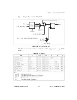
The SI, SI2, SC, and DIV counters each have their own control block. The counter control
blocks are synchronous control circuits that use the counter mode information, trigger and
gate signals, and state of the counter to generate the count enable and load control signals.
The state diagrams for the control circuits are discussed below.

