Chapter 3
Analog Output Timing/Control
©
National Instruments Corporation
3-117
DAQ-STC Technical Reference Manual
3.8.3 Analog Output Counters
The UI counter is a 24-bit binary down counter that generates update interval timing. The UI2
counter is a 16-bit binary down counter that generates a second independent update interval.
The UC counter is a 24-bit binary down counter that counts the number of UPDATEs. The
BC counter is a 24-bit binary down counter that counts the number of cycles or buffers
generated; that is, the TC of the UC counter. Notice UI2 does not have associated update or
buffer repetition counters. It is primarily intended to be used in an interrupt-driven waveform
generation where these functions are provided by software.
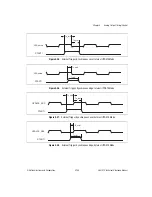
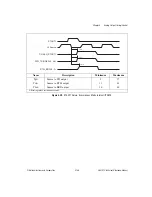
The UI counter alternate first period reload modes provide a retriggerable method for
obtaining a delay between the trigger signal and the first update pulse which is different than
the update interval.
The UI, UI2, UC, and BC counters each has its own control block. The counter control blocks
are synchronous control circuits that use the counter mode information, trigger and gate
signals, and state of the counter to generate the count enable and load control signals.
Figure 3-37 shows the state diagram for the UI control block. Figures 3-38 and 3-39 show the
state diagrams for the UC and BC control blocks, respectively.
3.8.3.1 UI Counter
The UI counter is a 24-bit down counter with dual-load registers. The UI counter typically
counts the interval between UPDATEs, as well as the delay from the initial trigger to the first
update. The bitfield AO_UI_Source_Select controls the selection of the UI source clock
(UI_SRC). The choices for UI source are AO_IN_TIMEBASE1, PFI<0..9>,
RTSI_TRIGGER<0..6>, and IN_TIMEBASE2. The bitfield AO_UI_Source_Polarity selects
the polarity of the source clock. The counter load registers are directly accessible from the
register map. If the counter is disarmed, AO_UI_Load loads the counter with the value from
the selected load register.
During normal operation, the UI counter synchronously reloads from the selected load
register following UI_TC. Several options—AO_UI_Reload_Mode,
AO_UI_Switch_Load_On_End, AO_UI_Switch_Load_On_Stop, and
AO_UI_Switch_Load_On_TC—exist for the UI counter to change the selected load register
under various conditions. The options are to alternate load registers once after each STOP,
switch load registers on every STOP, alternate load registers once after each BC_TC, switch
load registers on every BC_TC, switch load registers on the next BC_TC, switch load
registers on the next STOP, and switch load registers on the next UI_TC. The term alternate
load registers refers to the action of having one load from the secondary load register and the
remaining loads from the primary load register. The UI control circuit generates the count
enable signals.

