Chapter 4
General-Purpose Counter/Timer
DAQ-STC Technical Reference Manual
4-58
©
National Instruments Corporation
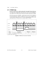
4.7.6 CTRGATE Setup
In many GPCT functions (for example, simple gated event counting) the gate signal causes
the counter to start and stop counting. In these functions, CTRGATE is usually synchronized
to the falling edge of CTRSRC before being used by the counter. In order for CTRGATE to
be recognized, it must stabilize at least one setup time before the relevant edge of CTRSRC.
In the internal timing mode, CTRGATE is synchronized to the inactive edge of CTRSRC. In
the external timing mode, CTRGATE is synchronized to the active edge of CTRSRC before
it enters a delay gate. Figures 4-26 and 4-27, and the accompanying table indicate the setup
time requirements for CTRGATE relative to the relevant edge of CTRSRC.
Figure 4-26.
CTRGATE Setup Timing, Internal Timing Mode
Name
Description
Minimum
Maximum
Tgtclk
CTRGATE to CTRSRC setup
8
—
All timing values are in nanoseconds.
CTRSRC
Tgtclk
Counter
2
1
1
1
1
0
N
N-1
N-2
Counter TC
CTRGATE
Tgtclk

