Chapter 3
Analog Output Timing/Control
DAQ-STC Technical Reference Manual
3-70
©
National Instruments Corporation
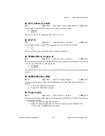
AO_UC_Save_Value
bits: <0..7>
type: Write
in: AO_UC_Save_Registers
address: 20
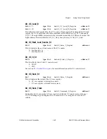
bits: <0..15>
type: Write
in: AO_UC_Save_Registers
address: 21
When AO_UC_Save_Trace is 0, this bitfield reflects the contents of the UC counter. When
you set AO_UC_Save_Trace to 1, this bitfield synchronously latches the contents of the UC
counter using the UC source. The eight MSBs are located at the lower address and the 16
LSBs are located at the higher address. Related bitfields: AO_UC_Save_Trace.
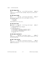
AO_UC_Switch_Load_Every_BC_TC
bit: 12
type: Write
in: AO_Mode_3_Register
address: 70
This bit enables the UC counter to switch load registers on BC_TC:
0: Disabled.
1: Enabled.
AO_UC_Switch_Load_Every_TC
bit: 2
type: Write
in: AO_Mode_1_Register
address: 38
This bit enables the UC counter to switch load register on UC_TC:
0: Disabled.
1: Enabled.
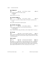
AO_UC_Switch_Load_On_BC_TC
bit: 6
type: Strobe
in: AO_Command_2_Register
address: 5
Setting this bit to 1 causes the UC counter to switch load registers at the next BC_TC. This
action is internally synchronized to the falling edge of the UC_CLK. This bit is cleared
automatically.
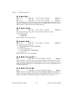
AO_UC_Switch_Load_On_TC
bit: 5
type: Strobe
in: AO_Command_2_Register
address: 5
Setting this bit to 1 causes the UC counter to switch load registers at the next UC_TC. This
action is internally synchronized to the falling edge of the UC_CLK. This bit is cleared
automatically.
AO_UC_TC_Interrupt_Ack
bit: 7
type: Strobe
in: Interrupt_B_Ack_Register
address: 3
Setting this bit to 1 clears AO_UC_TC_St and acknowledges the UC_TC interrupt request
(in either interrupt bank) if the UC_TC interrupt is enabled. This bit is cleared automatically.
Related bitfields: AO_UC_TC_St.

