Chapter 2
Analog Input Timing/Control
©
National Instruments Corporation
2-111
DAQ-STC Technical Reference Manual
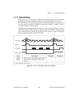
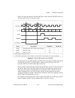
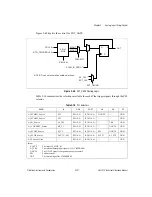
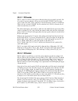
Figure 2-44 shows the timing for the halt-gating mode with an internal CONVERT, where the
SI2 source and SI source are the same signal.
Figure 2-44.
Halt-Gating Mode Timing, Internal CONVERT
The gate signal is always latched and recognized in the level-sensitive synchronous mode and
is qualified by the SCAN_IN_PROG signal. A change in the GATE signal is not used
internally while the SCAN_IN_PROG signal is asserted.
The recognition of the external gate signal in halt-gating mode is relative to the source clock
and the SI counter. The external gate signal is latched on the falling edge and used on the
rising edge, but it must be recognized prior to or at the same source clock edge as the SI
counter counting down to zero. The SI counter stops at one and remains there until the
external gate signal is deasserted. At that point the SI counter will decrement and generate the
START signal, which begins the next scan.
The timing for the halt-gating mode with an external CONVERT or with SI2 source and SI
source as different signals is more complicated and is, therefore, omitted.
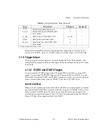
Name
Description
Minimum
Maximum
Tgtclk
External gate to SI2_Source setup internal
0
—
Tgtoff
Gate off a scan
(0)
—
Tgton
Gate on a scan
(0)
—
All timing values are in nanoseconds.
* The numbers in parentheses refer to the number of clock periods because those parameters are clock-edge driven.
SI2 Source
START
SI_CNT
CONVERT
External Gate
Tgtclk
Tgtclk
Tgtoff
Tgton
2
1
1
1
1
0
N
N-1
N-2
N-3

