Chapter 2
Analog Input Timing/Control
DAQ-STC Technical Reference Manual
2-126
©
National Instruments Corporation
2.8.3.3 SI Counter
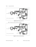
The SI counter is a 24-bit down counter with dual-load registers. The SI counter counts the
interval between internal STARTs, as well as the delay from the initial trigger to the start of
the first internal or external START. The bitfield AI_SI_Source_Polarity selects the polarity
of the source clock (SI_SRC). The counter load registers are directly accessible in write mode
from the register map. If the counter is disarmed, AI_SI_Load will load the counter with the
value from the selected load register. The AI_SI_Write_Switch option allows the load register
writes to be directed to the inactive load register.
During normal operation, the SI counter will synchronously reload from the selected load
register following SI_TC. Several options exist (AI_SI_Reload_Mode,
AI_SI_Switch_Load_On_END, AI_SI_Switch_Load_On_STOP, and
AI_SI_Switch_Load_On_TC) for the SI counter to change the selected load register under
various conditions. The options are: alternate load registers once after each STOP; switch load
registers on every STOP; alternate load registers once after each SC_TC; switch load registers
on every SC_TC; switch load registers on the next SC_TC; switch load registers on the next
STOP; switch load registers on the next SI_TC.
The term alternate load registers refers to the action of having one load from the secondary
load register and the remaining loads from the primary load register. The SI control circuit
generates the count enable signals.
2.8.3.4 SI Control
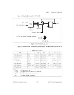
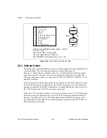
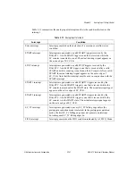
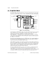
The SI counter is controlled by a circuit whose state transitions are shown in Figure 2-50. The
SI counter control circuit has two states: WAIT1 and CNT1. On power up, the control circuit
begins in state WAIT1 and remains there until the counter is armed and a START1 pulse is
received. When these two events occur, the counter moves to the CNT1 state and begins
generating START signals (internal START) or begins counting the START holdoff (external
START). On SC_TC, the required number of STARTs has been generated and the counter
returns to the WAIT1 state.
The SI load signal (SI_LOAD) enables the SI counter to reload from the selected load register
on the next clock. SI_LOAD is asserted when SI_TC is reached or is asserted by software
(AI_SI_Load).
The SI count enable signal (SI_CE) allows the SI counter to count. SI_CE asserts on any
transition terminating at either the CNT1 or CNT2 state, provided that the SI counter is armed
(AI_SI_Arm).
The SI disarm signal (SI_DISARM) clears the AI_SI_Arm bit in the register map.
SI_DISARM asserts on the transition from the CNT1 to the WAIT1 state when
AI_End_On_End_Of_Scan, AI_End_On_SC_TC, or AI_Trigger_Once is high.

